Download
1 / 96
960 likes | 1.06k Vues
OFDM-based Terrestrial Geolocation. Authors:. Abstract

E N D
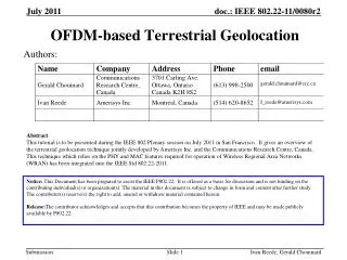
Ivan Reede, Gerald Chouinard OFDM-based Terrestrial Geolocation Authors: Abstract This tutorial is to be presented during the IEEE 802 Plenary session on July 2011 in San Francisco. It gives an overview of the terrestrial geolocation technique jointly developed by Amerisys Inc. and the Communications Research Centre, Canada. This technique which relies on the PHY and MAC features required for operation of Wireless Regional Area Networks (WRAN) has been integrated into the IEEE Std 802.22-2011. Notice: This Document has been prepared to assist the IEEE P802.22. It is offered as a basis for discussion and is not binding on the contributing individual(s) or organization(s). The material in this document is subject to change in form and content after further study. The contributor(s) reserve(s) the right to add, amend or withdraw material contained herein. Release:The contributor acknowledges and accepts that this contribution becomes the property of IEEE and may be made publicly available by P802.22.
Ivan Reede, Gerald Chouinard Outline • Fine ranging using OFDM • Fine ranging in OFDM systems • Sampling rate barrier paradigm • Fine ranging operating principle • Fine ranging process between BS and CPE • The ‘Vernier’ process • Construction of the “high-resolution” CIR function • Results of simulations • Results of measurements • Multipath excess delay time span • Geolocation process with one BS and two CPEs • Conclusions
Ivan Reede, Gerald Chouinard Outline • Fine ranging using OFDM • Fine ranging in OFDM systems • Sampling rate barrier paradigm • Fine ranging operating principle • Fine ranging process between BS and CPE • The ‘Vernier’ process • Construction of the “high-resolution” CIR function • Results of simulations • Results of measurements • Multipath excess delay time span • Geolocation process with one BS and two CPEs • Conclusions
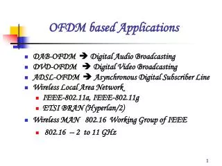
Ivan Reede, Gerald Chouinard Fine ranging in OFDM Systems • High accuracy ranging (+/-15 m) is required to geolocate terminals (Latitude and Longitude) within 50 m (FCC) • OFDM systems inherently obtain channel impulse response information (CIR) for their operation • Channel distortion characterized by such CIR information is usually • Annoying for communication systems • Need to be compensated to improving communication performance • Such information will now be shown to be valuable to carry out fine ranging
Ivan Reede, Gerald Chouinard Fine ranging in OFDM Systems • OFDM systems inherently transmit • A set of coherent pilot carriers (carriers are at slightly different frequencies at RF, but are harmonically related at baseband, all transmitted simultaneously) • The transmission channel • Introduces a complex warping in the signal • Caused by multipath due to reflections and dispersion • The sampling time shift at the receiver • Sampling time at the receiver, with respect to the sampling time used to build the signal, can introduce a shift that results in an additional warping of the signal in the frequency domain • OFDM receivers sample the complex warped signal
Ivan Reede, Gerald Chouinard Fine ranging in OFDM Systems • Current receiver designs use preambles and pilot carriers to align the constellation demodulation process • OFDM receivers demodulate with known phase resolutions QPSK Constellation 16-QAM Constellation 64-QAM Constellation To demodulate QPSK phase lock must be much better than ±45° To demodulate 16-QAM phase lock must be much better than ±19° To demodulate 64-QAM phase lock must be much better than ±7.5°
Ivan Reede, Gerald Chouinard Starting discontinuity Tail end always aligns with the starting discontinuity OFDM Cyclic Prefix
Ivan Reede, Gerald Chouinard OFDM Cyclic Prefix Starting discontinuity has been masked by copying tail end and inserting it as a cyclic prefix
Ivan Reede, Gerald Chouinard OFDM Cyclic Prefix Initial filter ringing and inter-symbol interference has the time to decay before acquisition begins
Ivan Reede, Gerald Chouinard OFDM Cyclic Prefix use Signal acquisition interval does not have to be precisely aligned to get a valid orthogonal signal set
Ivan Reede, Gerald Chouinard Outline • Fine ranging using OFDM • Fine ranging in OFDM systems • Sampling rate barrier paradigm • Fine ranging operating principle • Fine ranging process between BS and CPE • The ‘Vernier’ process • Construction of the “high-resolution” CIR function • Results of simulations • Results of measurements • Multipath excess delay time span • Geolocation process with one BS and two CPEs • Conclusions
Ivan Reede, Gerald Chouinard Sampling Rate Barrier Paradigm • For 802.22, the sampling period is 146 nsec • (sampling frequency ≈ 8/7*6 MHz channel bandwidth) • We will show that this is not the time resolution barrier • At first glance, it appears that • One can't obtain information to a finer resolution than the sampling period • This has proven to be a false impression • Since channel bandwidth limitation provided by receiver analog filtering prevents aliasing • Nyquist criterion is met and information below this sampling barrier is then recoverable.
Ivan Reede, Gerald Chouinard Sampling Rate Barrier Paradigm • IFFT processing usually preserves • The real values of CIR output components • Discarding the imaginary component of CIR • Causes the apparent sampling rate timing barrier • The imaginary component of the CIR • Embeds precious timing information
Ivan Reede, Gerald Chouinard Sampling Rate Barrier Paradigm • Combining both real and imaginary components allows for very fine correlation and interpolation
Ivan Reede, Gerald Chouinard OFDM receivers sample at regular discrete intervals in time
Ivan Reede, Gerald Chouinard Sampling decimates timing information thereby creating an ambiguity window
Ivan Reede, Gerald Chouinard Impulse signal and its frequency representation
Ivan Reede, Gerald Chouinard Delayed signal and its frequency representation
Ivan Reede, Gerald Chouinard Sampling time and phase of multiple carriers
Ivan Reede, Gerald Chouinard Stimulus 146 ns Fractional sampling time echo shift and its phase information Shift= -0.5 sampling period
Ivan Reede, Gerald Chouinard Stimulus 146 ns Fractional sampling time echo shift and its phase information Shift= -0.4 sampling period
Ivan Reede, Gerald Chouinard Stimulus 146 ns Fractional sampling time echo shift and its phase information Shift= -0.3 sampling period
Ivan Reede, Gerald Chouinard Stimulus 146 ns Fractional sampling time echo shift and its phase information Shift= -0.2 sampling period
Ivan Reede, Gerald Chouinard Stimulus 146 ns Fractional sampling time echo shift and its phase information Shift= -0.1 sampling period
Ivan Reede, Gerald Chouinard Stimulus 146 ns Fractional sampling time echo shift and its phase information Shift= +0.0 sampling period
Ivan Reede, Gerald Chouinard Stimulus 146 ns Fractional sampling time echo shift and its phase information Shift= +0.1 sampling period
Ivan Reede, Gerald Chouinard Stimulus 146 ns Fractional sampling time echo shift and its phase information Shift= +0.2 sampling period
Ivan Reede, Gerald Chouinard Stimulus 146 ns Fractional sampling time echo shift and its phase information Shift= +0.3 sampling period
Ivan Reede, Gerald Chouinard Stimulus 146 ns Fractional sampling time echo shift and its phase information Shift= +0.4 sampling period
Ivan Reede, Gerald Chouinard Stimulus 146 ns Fractional sampling time echo shift and its phase information Shift= +0.5 sampling period
Ivan Reede, Gerald Chouinard The Barrier is Broken ! • Sampling rate is not the ‘time of arrival’ resolution limit • Determination of the time of arrival of each specular or discrete echo is not limited by the sampling rate and can be precisely determined • The precise time of arrival of an echo within the sampling period can be deduced from it phase. • Only limited by the A/D and FFT/IFFT resolution (bits/sample) • Signal bandwidth limits the dispersion resolution • Nyquist limit determines how close echoes can be before they will appear as clumped together and cannot be discriminated: • Nyquist limit = 1/BW = 1/5.63 MHz = 178 ns = 59 m • (More practical limits= 68 m between 2 equal amplitude echoes 76 m between echoes with 7 dB difference)
Ivan Reede, Gerald Chouinard Outline • Fine ranging using OFDM • Fine ranging in OFDM systems • Sampling rate barrier paradigm • Fine ranging operating principle • Fine ranging process between BS and CPE • The ‘Vernier’ process • Construction of the “high-resolution” CIR function • Results of simulations • Results of measurements • Multipath excess delay time span • Geolocation process with one BS and two CPEs • Conclusions
Ivan Reede, Gerald Chouinard Fine ranging operating principle • Uses the normal OFDM encoding and decoding process on specific ranging symbols • Uses PN-sequence known at both terminals to modulate the carriers
Ivan Reede, Gerald Chouinard Fine ranging operating principle • OFDM can generate bandwidth limited repetitive classic Dirac-like RADARpulse if PN = 1 + j0 (with DC carrier removed) OFDM bandwidth limited Dirac pulse train with DC carrier removed
Ivan Reede, Gerald Chouinard Fine ranging operating principle • OFDM can generate all possible bandwidth limited repetitive signals with other known complex PN sequences Amplitude Normalized time samples Amplitude Normalized time samples
Ivan Reede, Gerald Chouinard Fine ranging operating principle • Cyclic prefix is added to absord echoes and eliminate ISI • The channel generally alters the signal waveform due to echoes, reflections and dispersion • Propagation delays distorts and attenuates the signal
Ivan Reede, Gerald Chouinard Fine ranging operating principle • The OFDM receiver amplifies and samples the received waveform • Normally uses a synch advance into the cyclic prefix:(to avoid ISI due to pre-echoes)
Ivan Reede, Gerald Chouinard Fine ranging operating principle • The OFDM receiver performs an FFT on the received samples
Ivan Reede, Gerald Chouinard Fine ranging operating principle • The known complex PN sequence is removed: Y/X • The result is: • A mathematical representation of the complex channel impulse response in the frequency domain • Normally used to correct the carrier constellation for proper data decoding Up to this point, normal OFDM receiver operation
Ivan Reede, Gerald Chouinard Fine ranging operating principle • This channel impulse response is practically identical to that of a classic Dirac Pulse RADAR in the frequency domain • This channel impulse response will be used for fine ranging calculations • These calculations can all be done by an off-line processor (e.g., at the NOC) • Practically no hardware costs ! • No wiring • No additional antenna • No additional installation • Guaranteed co-location • Tamper resistant
Ivan Reede, Gerald Chouinard Outline • Fine ranging using OFDM • Fine ranging in OFDM systems • Sampling rate barrier paradigm • Fine ranging operating principle • Fine ranging process between BS and CPE • The ‘Vernier’ process • Construction of the “high-resolution” CIR function • Results of simulations • Results of measurements • Multipath excess delay time span • Geolocation process with one BS and two CPEs • Conclusions
Ivan Reede, Gerald Chouinard Propagation time between Base Station and CPE(Coarse Time Difference of Arrival: TDOA) A1 Downstream RNG-RSP > Upstream < RNG-REQ CPE BS CPE synchronizes with BS and is in phase-lock with the RF carrier.The sampling frequency (≈ 8/7*BW) is derived from the same clock BS and CPE carry out normal association and ranging and adjust the advance A1 so that all CPE upstream bursts arrive at the BS at the same time independently of their distance, within ±25% of the smallest cyclic prefix (±2.33 sec) A1 is regularly updated by the ranging process, in sampling clock units, TU≈1/(8/7*BW) (e.g., 145.8576 ns for 6 MHz) A1 roughly corresponds to double the BS-CPE distance: BS-CPE distance = 1/2 * A1*145.8*0.3 (m)
Ivan Reede, Gerald Chouinard Propagation time between Base Station and CPE(Fine Time Difference of Arrival: TDOA) A1 Downstream RNG-RSP > T1 DCPE Upstream T2 < RNG-REQ CPE BS TTG BS transmits a RNG-RSP to the specific CPE and initiates its counter T1 (in sampling intervals: TU’s) at the moment where the downstream burst leaves the BS (at the start of the frame preamble). The BS knows exactly the symbols on which the solicited Ranging burst will be transmitted by the CPE on the upstream since it is registered in the US-MAP. The BS keeps this value T2 in memory The BS knows the size of the TTG in TU’s (e.g., 1439 TU for 6 MHz), The precise residual CPE time delay DCPE is sent to the BS at initialization (measured with an accuracy of at least +/-30 ns in a test setup corresponding to the CPE being co-located with the BS and A1 set to zero). Note:A1, the advance obtained through coarse ranging, is known at the BS.
Ivan Reede, Gerald Chouinard Solicited CDMA Ranging burst TTG+T2 DS-MAP for the RNG-RSP MAC message US-MAP for the CDMA Ranging burst RNG-RSP MAC message 802.22 Frame structure Reference start time for T1 counter An example of a RNG-RSP and RNG-REQ exchange between BS and CPE.
Ivan Reede, Gerald Chouinard Propagation time between Base Station and CPE(Fine Time Difference of Arrival: TDOA) Vernier-1 Downstream RNG-RSP > T1 DCPE Upstream T2 < RNG-REQ CPE BS TTG Vernier-1 uses the information on the frequency domain equalization process done at the CPE to precisely calculate the arrival of the first multipath relative to the synchronization time at the CPE recovered by the receiver synchronization: (Note that an advance of a few TU’s will normally be inserted by the CPE synchronization scheme to avoid ISI due to pre-echoes.) The CPE responds by sending a ranging burst during the frame specified in the RNG-CMD message and at the specified symbol offset T2. BS receives the ranging burst and stops the T1 counter at the arrival of the ranging burst, precisely at the time of the first sampling period belonging to the burst. (T1counter is in sampling periods, TU’s, at the BS.)
Ivan Reede, Gerald Chouinard Vernier time reference Channel impulse response Symbol period Cyclic prefix Reference 2k FFT sampling window Time reference for the FFT window during symbol generation at the transmitter where the residual phases calculated by the Vernier are zero. Synchronized 2k FFT sampling window Time reference for the FFT window at the receiver resulting from the synchronization scheme using the preamble plus an advance of a number of samples to avoid pre-echo leakage) Typical Vernier value (ns) (including all received multipaths)
Ivan Reede, Gerald Chouinard Propagation time between Base Station and CPE(Fine Time Difference of Arrival: TDOA) Vernier-1 Downstream RNG-RSP > T1 DCPE Upstream T2 < RNG-REQ Vernier-2 CPE BS TTG BS acquires the I&Q values of the ranging burst carriers at the output of the FFT (Vernier-2) and removes the PN-sequence. Off-line signal processing can be applied onto the received 168 reference upstream subcarriers to resolve the precise time of arrival (ns) of the first multipath relative to the reference sampling time at the BS (V2). The values of the frequency domain vector of Vernier-1 that were acquired during the downstream burst is queried later by the BS The CPE sends these values (1680 I&Q values coded in 8 bits) to the BS. Once the Vernier-1 vector is acquired by the BS, signal processing can be performed off-line. The precise delay (ns) of the first channel echo relative to the synchronization reference at the CPE can be extracted: V1.
Ivan Reede, Gerald Chouinard Propagation time between Base Station and CPE(Fine Time Difference of Arrival: TDOA) Vernier-1 Downstream RNG-RSP > T1 DCPE Upstream T2 < RNG-REQ Vernier-2 CPE BS TTG BS knows:TTG in sampling periods TU’s (e.g., 1439 TU for 6 MHz),T2 in symbols from the scheduling of the ranging burst,DCPE representing the precise delay inherent to the CPE,T1 from the stopped counter in sampling periods,V1 from the processing of the acquired Vernier-1 vector in ns,V2 from the processing of the acquired Vernier-2 vector in ns. All the information necessary to calculate the propagation time between the BS and CPE is known down to a nanosecond accuracy:Ptime = T1 - (T2 + TTG) - DCPE + V1 + V2 (ns)Distance = c * Ptime/2 (m)
Ivan Reede, Gerald Chouinard Outline • Fine ranging using OFDM • Fine ranging in OFDM systems • Sampling rate barrier paradigm • Fine ranging operating principle • Fine ranging process between BS and CPE • The ‘Vernier’ process • Construction of the “high-resolution” CIR function • Results of simulations • Results of measurements • Multipath excess delay time span • Geolocation process with one BS and two CPEs • Conclusions
Ivan Reede, Gerald Chouinard The ‘Vernier’ process