Download
1 / 32
490 likes | 1.2k Vues
2.9 : AM Receiver. AM demodulation is the reverse process of AM modulation. A conventional double sideband AM receiver converts the amplitude-modulated waveform back to the original source by receiving, amplifying and demodulating the wave.

E N D
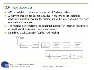
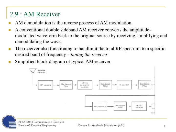
2.9 : AM Receiver • AM demodulation is the reverse process of AM modulation. • A conventional double sideband AM receiver converts the amplitude-modulated waveform back to the original source by receiving, amplifying and demodulating the wave. • The receiver also functioning to bandlimit the total RF spectrum to a specific desired band of frequency – tuning the receiver • Simplified block diagram of typical AM receiver BENG 2413 Communication Principles Faculty of Electrical Engineering
2.9 : AM Receiver • RF section (Receiver front end) • used to detect, bandlimit and amplifying the received RF signal. • Mixer/converter • Down-converts the received RF frequencies to intermediate frequencies (IF). • Intermediate frequencies are the frequencies that fall somewhere between the RF and the information frequencies. • IF section • Used for amplification and selectivity. • AM detector • Demodulates the AM wave and converts it to the original information signal. • Audio section • Used to amplify the recovered signal BENG 2413 Communication Principles Faculty of Electrical Engineering
2.9.1 : Receiver Parameters2.9.1.1 : Selectivity • Selectivity – parameter used to measure the ability of the receiver to accept a given band of frequencies and reject all others. • Ex : for the commercial AM broadcast band, each stations transmitter is allocated a 10 kHz bandwidth. For a receiver to select only those frequencies assigned in a single channel, the receiver must limit its bandwidth to 10 kHz. • A method to describe the selectivity of the receiver is to give the receiver a bandwidth at 2 levels of attenuation (e.g. -3 dB and -60 dB). • The ratio of these 2 bandwidths is called as shape factor (SF), (31) • In ideal, both bandwidth would be equal and the value of the shape factor would be 1. But this is impossible to be achieve in practical circuit. • Ex :AM broadcast-band radio receiver : SF = 2 satellite, microwave & 2-way radio receivers: SF = closer to 1 BENG 2413 Communication Principles Faculty of Electrical Engineering
2.9.1.1 : Selectivity • A radio receiver must be capable of separating the desired channel’s signal without allowing interference from an adjacent channel to spill over into the desired channel’s passband. BENG 2413 Communication Principles Faculty of Electrical Engineering
2.9.1.2 : Bandwidth Improvement • Thermal noise is one form of noise occurs in communication system that is proportional to a bandwidth. • As signal propagates from the antenna through the RF section, mixer/converter section and IF section, the bandwidth of signal is reduced thus reducing the noise. • Noise reduction ratio achieved by reducing the bandwidth is called bandwidth improvement (BI) expressed as follow, (32) where BI = bandwidth improvement BRF = RF bandwidth BIF = IF bandwidth BENG 2413 Communication Principles Faculty of Electrical Engineering
2.9.1.3 : Bandwidth Improvement • The corresponding reduction in noise due to reduction in bandwidth is called as noise figure improvement (33) • Ex 5-1 BENG 2413 Communication Principles Faculty of Electrical Engineering
2.9.1.4 : Sensitivity • Sensitivity of the receiver is defined as - the minimum RF signal level that can be detected at the input to the receiver and still produce a usable demodulated information signal. • Signal-to-noise ratio (SNR) and the power of signal at the output of the audio section are used to determine the quality of the received signal and whether it is usable. • Typical AM broadcast-band receivers, a 10 dB or more SNR with approximately 0.5W of signal power at audio section is considered usable. • Sensitivity of a receiver is expressed in microvolts of the received signal. • Typical sensitivity for commercial broadcast-band AM receiver is 50 μV. • Sensitivity of the receiver depends on : • Noise power present at the input to the receiver • Receiver noise figure • Sensitivity of the AM detector • Bandwidth improvement factor of the receiver • The best way to improve the sensitivity is to reduce the noise level BENG 2413 Communication Principles Faculty of Electrical Engineering
2.9.1.5 : Dynamic range • Dynamic range of a receiver is defined as - the difference in decibels between the minimum input level necessary to recognize a signal and the input level that will overdrive the receiver and produce distortion. • The minimum received levelis a function of the desired signal quality, front-end noise and the noise figure of the receiver : X • The level that will produce overload distortion is a function of the net gain of the receiver (total gain of all stages in the receiver) : Y • A dynamic range of 100 dB (between X and Y) is considered about the highest possible. • A low dynamic range can cause severe intermodulation distortion. BENG 2413 Communication Principles Faculty of Electrical Engineering
2.9.1.6 : Fidelity • Fidelity is defined as – a measure of the ability of a communication system to produce an exact replica of the original source information at the output of the receiver. • Any variations in the demodulated signal that are not in the original information signal is considered as distortion. • 3 forms of distortions : • Phase distortion • Amplitude distortion • Frequency distortion • Phase distortion • Filtering is the predominant cause of phase distortion • Frequencies at or near the break frequency of a filter undergo varying the values of the phase shift (i.e. the phase is shifted/delayed). • If all the frequencies are not delayed by the same amount of time, the frequency-versus-phase relationship of the received signal is not consistent with the original signal and the recovered signal is distorted. BENG 2413 Communication Principles Faculty of Electrical Engineering
2.9.1.6 : Fidelity • Amplitude distortion • Occurs when the amplitude-versus-frequency characteristics of the output signal of a receiver differs from those of the original signal. • It is the result of nonuniform gain in amplifiers and filters • Frequency distortion • Occurs when frequencies that are present in a received signal are not present in the original source information. • It is a result of harmonic and intermodulation distortion and caused by nonlinear amplification BENG 2413 Communication Principles Faculty of Electrical Engineering
2.9.1.7 : Insertion Loss • Insertion loss – ratio of the power transferred to a load with a filter in the circuit to the power transferred to a load without a filter in the circuit • Filters are generally constructed from lossy components such as resistorand imperfect capacitor that tend to attenuate (reduce the magnitude) the signal BENG 2413 Communication Principles Faculty of Electrical Engineering
2.9.1.8 : Noise Temperature/Equivalent Noise Temperature • Thermal noise is directly proportional to temperature and can be expressed in degress as well as watts and volts. where T = environmental temperature (kelvin) N = Noise power (watts) K = Boltsmann’s constant (1.38 x 10⁻²³ J/K) B = bandwidth (Hz) BENG 2413 Communication Principles Faculty of Electrical Engineering
2.9.2 : Types of receiver • 2 basic types of receiver • Coherent receiver – the frequencies generated in the receiver and used for demodulation are synchronized to oscillator frequencies generated in the transmitter. • Noncoherent receiver – frequencies that are generated in the receiver or the frequencies that are used for demodulation are completely independent from the transmitter’s carrier frequency • For AM DSBFC scheme, the noncoherent receivers are typically used. • Tuned Radio Frequency receiver (TRF) • Superheterodyne Receiver BENG 2413 Communication Principles Faculty of Electrical Engineering
2.9.2.1 : Tuned Radio Frequency Receiver (TRF) • Block diagram of 3-stages TRF receiver that includes an RF stage, a detector stage and an audio stage : • Two or three RF amplifiers are required to filter and amplify the received signal to a level sufficient to drive the detector stage. • The detector converts RF signals directly to information. • An audio stage amplifies the information signals to a usable level • Simple and have a relatively high sensitivity BENG 2413 Communication Principles Faculty of Electrical Engineering
2.9.2.1 : Tuned Radio Frequency Receiver (TRF) • 3 distinct disadvantages : 1. The bandwidth is inconsistent and varies with the center frequency when tuned over a wide range of input frequencies. • As frequency increases, the bandwidth = f/Q increases. Thus, the selectivity of the input filter changes over any appreciable range of input frequencies. • Ex 5-2 2. Instability due to large number of RF amplifiers all tuned to the same center frequency • High frequency, multi stage amplifiers are susceptible to breaking into oscillation. 3. The gains are not uniform over a very wide frequency range. • The nonuniform L/C ratios of the transformer-coupled tank circuits in the RF amplifiers. BENG 2413 Communication Principles Faculty of Electrical Engineering
2.9.2.2 : Superheterodyne Receiver • Heterodyne – to mix two frequencies together in a nonlinear device or to transmit one frequency to another using nonlinear mixing. • Block diagram of superheterodyne receiver : BENG 2413 Communication Principles Faculty of Electrical Engineering
2.9.2.2 : Superheterodyne Receiver • 1. RF section • Consists of a pre-selector and an amplifier • Pre-selector is a broad-tuned bandpass filter with an adjustable center frequency used to reject unwanted radio frequency and to reduce the noise bandwidth. • RF amplifier determines the sensitivity of the receiver and a predominant factor in determining the noise figure for the receiver. • 2. Mixer/converter section • Consists of a radio-frequency oscillator and a mixer. • Choice of oscillator depends on the stability and accuracy desired. • Mixer is a nonlinear device to convert radio frequency to intermediate frequencies (i.e. heterodyning process). • The shape of the envelope, the bandwidth and the original information contained in the envelope remains unchanged although the carrier and sideband frequencies are translated from RF to IF. BENG 2413 Communication Principles Faculty of Electrical Engineering
2.9.2.2 : Superheterodyne Receiver • 3. IF section • Consists of a series of IF amplifiers and bandpass filters to achieve most of the receiver gain and selectivity. • The IF is always lower than the RF because it is easier and less expensive to construct high-gain, stable amplifiers for low frequency signals. • IF amplifiers are also less likely to oscillate than their RF counterparts. • 4. Detector section • Gambar • To convert the IF signals back to the original source information (demodulation). • Can be as simple as a single diode or as complex as a PLL or balanced demodulator. BENG 2413 Communication Principles Faculty of Electrical Engineering
2.9.2.2 : Superheterodyne Receiver • 5. Audio amplifier section • Comprises several cascaded audio amplifiers and one or more speakers BENG 2413 Communication Principles Faculty of Electrical Engineering
2.9.3 : Receiver Operation2.9.3.1 : Frequency Conversion • Frequency conversion in the mixer stage is identical to the frequency conversion in the modulator except that in the receiver, the frequencies are down-converted rather that up-converted. • In the mixer, RF signals are combined with the local oscillator frequency • The local oscillator is designed such that its frequency of oscillation is always above or below the desired RF carrier by an amount equal to the IF center frequency. • Therefore the difference of RF and oscillator frequency is always equal to the IF frequency • The adjustment for the center frequency of the pre-selector and the local oscillator frequency are gang-tune (the two adjustments are tied together so that single adjustment will change the center frequency of the pre-selector and at the same time change the local oscillator) • when local oscillator frequency is tuned above the RF – high side injection when local oscillator frequency is tuned below the RF – low side injection BENG 2413 Communication Principles Faculty of Electrical Engineering
2.9.3.2 : Frequency Conversion • Mathematically expressed : High side injection (33) Low side injection(34) BENG 2413 Communication Principles Faculty of Electrical Engineering
2.9.3.2 : Frequency Conversion • Illustration of the frequency conversion process for an AM broadcast-band superheterodyne receiver using high side injection : BENG 2413 Communication Principles Faculty of Electrical Engineering
2.9.3.2 : Frequency Conversion • Ex 5-3 BENG 2413 Communication Principles Faculty of Electrical Engineering
2.9.3.3 : Local oscillator tracking • Local oscillator tracking – the ability of the local oscillator in a receiver to oscillate either above or below the selected radio frequency carrier by an amount equal to the intermediate frequency throughout the entire radio frequency band. • With high side injection- local oscillator should track above the incoming RF carrier by a fixed frequency equal to fRF + fIF • With low side injection- local oscillator should track below the incoming RF carrier by a fixed frequency equal to fRF - fIF BENG 2413 Communication Principles Faculty of Electrical Engineering
2.9.3.4 : Image frequency • Image frequency – any frequency other than the selected radio frequency carrier that will produce a cross-product frequency that is equal to the intermediate frequency if allowed to enter a receiver and mix with the local oscillator. • It is equivalent to a second radio frequency that will produce an IF that will interfere with the IF from the desired radio frequency. • if the selected RF carrier and its image frequency enter a receiver at a same time, they both mix with the local oscillator frequency and produce different frequencies that are equal to the IF. • Consequently, 2 different stations are received and demodulated simultaneously BENG 2413 Communication Principles Faculty of Electrical Engineering
2.9.3.4 : Image frequency • The following figure shows the relative frequency spectrum for the RF, IF, local oscillator and image frequencies for a superheterodyn receiver using high side injection. • For a radio frequency to produce a cross product equal to IF, it must be displaced from local oscillator frequency by a value equal to the IF. • With high side injection, the selected RF is below the local oscillator by amount equal to the IF. • Therefore, the image frequency is the radio frequency that is located in the IF frequency above the local oscillator as shown above, i.e. (35) BENG 2413 Communication Principles Faculty of Electrical Engineering
2.9.3.4 : Image frequency • The higher the IF, the farther away the image frequency is from the desired radio frequency. Therefore, for better image frequency rejection, a high IF is preferred. • However, the higher the IF, it is more difficult to build a stable amplifier with high gain. I.e. there is a trade-off when selecting the IF for a radio receiver (image frequency rejection vs IF gain and stability) BENG 2413 Communication Principles Faculty of Electrical Engineering
2.9.3.5 : Image frequency rejection ratio • Image frequency rejection ratio (IFRR) – a numerical measure of the ability of a pre-selector to reject the image frequency • Mathematically expressed as, (36) where ρ= (fim/fRF) – (fRF/fim) Q = quality factor of a pre-selector • Once an image frequency has down-converted to IF, it cannot be removed. In order to reject the image frequency, it has to be blocked prior to the mixer stage. I.e. the bandwidth of the pre-selector must be sufficiently narrow to prevent image frequency from entering the receiver. BENG 2413 Communication Principles Faculty of Electrical Engineering
2.9.3.5 : Image frequency rejection ratio • Ex 5-5 BENG 2413 Communication Principles Faculty of Electrical Engineering
2.9.4 : Double Conversion Receivers • For good image rejection, relatively high IF is desired. However, for a high gain selective amplifiers that are stable, a low IF is necessary. • The solution fro above constrain is to use 2 intermediate frequencies, i.e. by using double conversion AM receiver. • The 1st IF is a relatively high frequency for good image rejection. • The 2nd IF is a relatively low frequency for good selectivity and easy amplification. BENG 2413 Communication Principles Faculty of Electrical Engineering
2.9.5 : Net Receiver Gain • Net receiver gain is simply the ratio of the demodulator signal level at the output of the receiver to the RF signal level at the input to the receiver. • In essence, net receiver gain is the dB sum of all gains to the receiver minus the dB sum of all losses. • Gains and losses found in a typical radio receiver : Net Receiver Gain GdB = gainsdB – lossesdB where gains = RF amplifier gain + IF amplifier gain + audio amplifier gain losses = pre-selector loss + mixer loss + detector loss BENG 2413 Communication Principles Faculty of Electrical Engineering
2.9.5 : Net Receiver Gain • Ex 5-8 BENG 2413 Communication Principles Faculty of Electrical Engineering