Download
1 / 22
220 likes | 352 Vues
RF source, volume and caesiated extraction simulations (e-dump). Ø . Midttun on behalf of the Linac4 ion source team and T. Kalvas Linac4 Ion Source Review 07.06.2011. Summary. Linac4 H - volume source H - 35 keV commissioning results H - 35 keV simulations

E N D
RF source, volume and caesiatedextraction simulations (e-dump) Ø. Midttun on behalf of the Linac4 ion source team and T. Kalvas Linac4 Ion Source Review 07.06.2011
Summary • Linac4 H- volume source • H- 35 keV commissioning results • H- 35 keV simulations • Comparison of H- emittance measurements and simulations at 35 keV • Vaporization of electron dump • Volume source, two upgrade proposals for 45 kV extraction • Concept 1: Electron dumping at low energy in Einzel lens • Concept 2: Electron dumping on intermediate electrode • Deliverables, manpower, milestones
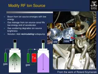
Linac4 H- volume source • Copy of the ion source for the Hadron Electron Ring Accelerator (HERA) at DESY, Hamburg • “Small” modifications • Increased extraction voltage from 35 kV to 45 kV • Increased H- current from 40 mA to 80 mA • Increased duty factor from 0.045% to 0.08% • Increased RF power from 30 kW to 100 kW • Following issues occurred from these modifications • High voltage breakdowns across insulators • Vaporization of the electron dump • Sparking in the antenna • We understand that we did not understand the system very well
H- 35 keV commissioning results • Stable beam pulse short term • High voltage breakdowns:15 per 24 hours, average over 12 days
H- 35 keV simulations • Vector Fields Opera SCALA/TOSCA • 3DElectromagnetic simulation • Used to optimize the dumping of the electrons • No simulation of particle extraction from a plasma. • Particles are extracted from a conductor. Shape of plasma meniscus is shaped/guessed to get a convergent solution • IH- = 36 mA • e/H = 50 • IBSimu • 3D simulation of particle extraction from a plasma • Modular software. This case: • Geometry imported as a DXF-file • Magnetic field imported from Opera • IH- = 36 mA • e/H = 50 e- beam Plasma meniscus H- beam
Comparison of H- emittance measurements and simulations at 35 keV Measurement setup Simulation SEM grid Slit Faraday Cup Source 1st part: Plasma extraction and electron dumping 2nd part: Drift through beam pipe to the slit 200 mm 200 mm
Beam projections comparison Position Angle • Comparison of measured (red) and simulated (green) beam projections • Beam projections corresponding well between measurements and simulations Horizontal Vertical
Emittance measurements and simulations at 35 keV (10% filtered) Horizontal Vertical Measured 0.28 mm mrad 0.36 mm mrad Simulated 1.06 mm mrad 0.70 mm mrad Differences due to binning size of plots, can be corrected It is difficult to make emittance comparisons when the shape is a thin line
Vaporization of electron dump at 35 keV Permanent B-field in the electron dump gives the electron beam a different curving radius for different energies. The beam is sweeping the surface when ramping up the beam energy from 0-35 keV for high voltage conditioning Carbon dump after 35 keV operation
IBSimu power density plots of electron dump e- beam 35 keV, 1.5 A, 500 μs Max power density 1.8 kW/mm2 e- beam 45 keV, 1.5 A, 100 μs Max power density 3.0 kW/mm2 Thermal simulations show that pulsed power densities above 1 kW/mm2 (for 500 μs pulses) will vaporize the dump surface 26 mm 26 mm
Volume source, two upgrade proposals for 45 kV extraction • A new concept should : • Reduce electron power density by lowering electron dumping energy and spread electron dumping surface • Have a less divergent beam at the entry of the LEBT • (Electrode potentials are given in kilovolts relative to ground) 1. e- dump in Einzel lens 2. e- dump in intermediate electrode -45 0 - 35 0 -45 - 40 -39 0
Electron dumping B-field • B-field simulation from Vector Fields Opera • Two permanent magnets inside Einzel lens creating a dipole field of ~ 30 mT (peak) • Magnetic shielding on both sides of Einzel lens and in the electron dump • Six permanent magnets in Halbach-type dipole configuration • Magnets are located in the collar • Maximum field ~ 65 mT 30 mm 10 mm
Concept 1: Beam optics depending on current and e/H ratio e/H = 5 e/H = 50 • Low current, low e/H ratio (IH- = 30, e/H = 5) • Plasma meniscus pushed back • Over-focused beam • Beam is divergent with a halo • High current, high e/H ratio (IH- = 80, e/H = 50) • Beam is exploding • High space charge is pushing electrons back into the extraction region • We need different settings for different current extractions • There exists a solution for the different cases IH- = 30 -45 0 - 35 0 -45 0 - 35 0 IH- = 80 -45 0 - 35 0 -45 0 - 35 0
Concept 1: Use puller voltage to optimize beam optics • Simulation with • IH- = 30 mA • e/H = 15 • Changing puller voltage to optimize beam optics • 0, -10, -20 kV • No mechanics needed • Allows operational adjustment -45 0 - 35 0 -45 -10 - 35 0 -45 -20 - 35 0
Concept 1: Correction beam position and angle by tilting and moving electrodes • Horizontal tilt and offset of either puller electrode or ground electrode • IH- = 30 mA • e/H = 50 • Possibility of optimizing beam position and angle -45 0 - 35 0 -45 0 - 35 0 Puller tilt (3°) and offset (2 mm) Ground tilt (3°) and offset (2 mm)
Concept 1: Puller tilt and offset influence on beam position and angle Average position of beam Average angle of beam Gives the possibility of correcting beam position and angle
Concept 1: Electron dump power density • Power density plot for the case • IH- 30 mA • e/H 50 • Max power density is 1.2 kW/mm2 • Reduced from the Linac4 case (3.0 kW/mm2) due to the lower electron energy • Dump needs to be optimized for spreading the beam on the surface • Thermal time behaviour needs to be studied further
Concept 1: Secondary electron emission • Example of secondary electron emission in IBSimu (non ideal case) • Yellow: Electrons • Red: Negative hydrogen • Purple: Secondary electrons • Electrons are escaping due to • Electron beam hitting the side wall of the dump • Part of H- beam touching inside the dump • The secondary electrons created in the bottom of the dump do not escape due to the high space charge region from the electron beam
Concept 2: Beam optics depending on current and e/H ratio 30 mA, e/H = 5 30 mA, e/H = 50 • For higher currents the e/H ratio has to be low • Study of secondary electron emission in progress -45 -40 -39 0 -45 -40 -39 0 80 mA, e/H = 5 80 mA, e/H = 50 -45 -40 -39 0 -45 -40 -39 0
Concept 2: Electron dump power density 30 mA, e/H = 5 30 mA, e/H = 50 80 mA, e/H = 5 80 mA, e/H = 50 In all cases, we stay below the surface vaporization limit
Summary • The Linac4 ion source commissioning results show that the beam extraction has to be modified for 45 keV operation • A study of two different concepts has started • Concept 1 – Electron dumping in Einzel lens • Results in lower electron power density • Works for different current densities without modifying geometry • Improved beam divergence • Beam can be corrected by electrode tilting • Concept 2 – Electron dumping on intermediate electrode • Results in lower electron power density • Works for different current densities • Improved beam divergence • Comparison of the two schemes still ongoing • We have the necessary tools to simulate dump power densities and to optimize H- beam extraction and electron dumping
Deliverables, manpower, milestones • Deliverables • Simulation of extraction system with IBSimu • Manpower • 2 FTE for IBSimu simulations and measurements • Milestones • Finished simulations for chosen extraction system concept by September 2011 (in parallel with source and extraction integration) • Start measurements by end of 2012 • Design of caesiated source extraction ready by end of 2012 • Measurements with caesiated source extraction system by end of 2013