Download
1 / 44
470 likes | 627 Vues
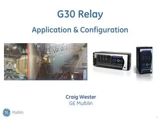
Part Three – Relay Input Sources. Wei-Jen Lee, Ph.D., PE Professor of Electrical Engineering Dept. The Univ. of Texas at Arlington. Introduction.

E N D
Part Three – Relay Input Sources Wei-Jen Lee, Ph.D., PE Professor of Electrical Engineering Dept. The Univ. of Texas at Arlington
Introduction • Protective relays require reasonably accurate reproduction of the normal, tolerable, and intolerable conditions in the power system fro correct sensing and operation. • This information input from the power system is usually through current and voltage transformers. • Some exceptions, such as temperature and vibration relays, which receive their information from other type of transducers.
Current Transformers • Typical CT ratio
Current Transformers • Current transformer performance on a symmetrical AC component • If the CT does not saturate, it is reasonable to assume that Ie is negligible. • However, the CT excitation current is never equal to zero. Thus, it must be checked to assure that it does not cause intolerable errors. • This can be done by one of the three methods: 1) classic transformer formula, 2) CT performance curves, or 3) ANSI/IEEE accuracy classes for relaying.
Current Transformers • Current transformer performance check • Classic analysis • The load of the CT consists of secondary resistance Rs, the impedance of he connecting leads Zld, and the equipment (relays and such) Zr. The voltage required by the burden (load) is
Current Transformers • Current transformer performance check • CT characteristic curves • The calculation of the performance with the equivalent circuit of Fig. 5.6a is difficult. • ANSI/IEEE (C53.71) classifies CTs that have significant leakage flux within the transformer core as class T (class H before 1968) • The class C (class L before 1968) is CTs constructed to minimize the leakage flux in the core that can represented by the Fig. 5.6b.
Current Transformers • Current transformer performance check • CT characteristic curves • The knee or effective point of saturation is defined by ANSI/IEEE standard as the intersection of the curve with 45o tangent line. • However, the IEC defines the knee as the intersection of straight lines extended from the nonsaturated and saturated parts of the exciting curve. • The IEC knee is higher voltage than the ANSO curve.
Current Transformers • Current transformer performance check • CT characteristic curves - Typical overcurrent ratio curve for class T CT
Current Transformers • Current transformer performance check • CT characteristic curves - Typical excitation curves for a multiratio class C CT
Current Transformers • Current transformer performance check • ANSI/IEEE standard accuracy class • In many applications, the use of ANSI/IEEE accuracy class designation is adequate to assure satisfactory relay performance. • Manufacturer’s test curves must be used for Class T CTs. • For class C, the designations are followed by a number indicating the secondary terminal voltage (Vgh) that the transformer can deliver to a standard burden at 20 times the rated secondary current without exceeding the 10% ratio correction.
Current Transformers • Current transformer performance check • ANSI/IEEE standard accuracy class
Current Transformers • Current transformer performance check • ANSI/IEEE standard accuracy class • For relaying, the voltage classes are 100, 200, 400, and 800, corresponding to standard burdens of B-1, B-2, B-4, and B-8, respectively. • These burdens are at 0.5 power factor. • If the current is lower, the burden can be higher in proportion. • The lower voltage classes of 10, 20, and 50 with standard burdens of B-0.1, B-0.2, and B-0.5 at 0.9 power factor are primary for metering service and should be used very cautiously for protection.
Current Transformers • Current transformer performance • Two similar CTs connected in the primary circuit, with the same ratio and their secondaries in series, will increase the accuracy capability. • Two similar CTs, with their secondaries in parallel, provides an overall lower ratio with higher-ratio individual CTs and their correspondingly higher accuracy rating.
Current Transformers • Current transformer performance • ANSI classification does not provide actual value of error. • Also, the accuracy class only applies to the full winding and reduces proportionally when lower taps are available and used.
Current Transformers • Current transformer performance • IEC specifies the accuracy of the current transformers as: XX VA Class YY P ZZ where XX: Continuous VA (2.5, 5, 10, 15, and 30) YY: Accuracy class (5 and 10%) P: For protection ZZ: Accuracy limit factor (5, 10, 15, 20, and 30) Rated secondary amperes: 1, 2, and 5 A
Current Transformers • Secondary burdens during faults
Current Transformers • Secondary burdens during faults
Current Transformers • Secondary burdens during faults
Current Transformers • CT selection and performance evaluation for phase faults • Assumption • Imax load = 90A, Imax fault= 2500A, and Imin. fault = 350A. • CT ratio selection • The conventional practice, over many years, has been that the secondary current should be just under 5A for the maximum load. Therefore, select CT ratio of 100/5 in this case.
Current Transformers • CT selection and performance evaluation for phase faults • Select relay tap for the phase-overcurrent relay • The tap should be higher than 4.5 A • Small tap 5 is selected • Minimum fault of 350/20=17.5 A, and 17.5/5=3.5 times the minimum relay pick up. This is desirable for any possible fault restriction. • If tap 6 is selected, then the margin above the load is greater (6/4.5=1.33), but a smaller margin (17.5/6=2.9) above the relay pick up.
Current Transformers • CT selection and performance evaluation for phase faults • Determine the total secondary burden • The total connected secondary load determination must include all of the impedance between the CTs and the equipment in the phase circuit. • Assume tap 5 is used and the burden is 2.64 VA at 5A and 580 VA at 20X. Also, the lead from the CT to relay is 0.4W. • The total secondary impedance at pick up: Relay burden 2.64/52 = 0.106W Lead resistance = 0.40W Total impedance to CT terminals = 0.506W at 5A
Current Transformers • CT selection and performance evaluation for phase faults • Determine the total secondary burden • The total secondary impedance at 20X: Relay burden 580/1002 = 0.058W Lead resistance = 0.40W Total impedance to CT terminals = 0.458W at 100A • It is frequently practical to add the burden impedance and the current algebraically (they should be combined phasorally) • Burdens are generally near unity power factor; hence Is tends to be near unity power factor. Ie (the excitation current) is around 90o lagging. Combine Is and Ie at right angle is a good approximation.
Current Transformers • CT selection and performance evaluation for phase faults • Determine the CT performance • When using a class T CT • Use the provided curves. • Use actual relay burden (0.506 or 0.458 in this case) • When using a class C CT and performance by ANSI/IEEE standard • If a 600/5 multiratio CT with C100 rating is selected. Vgh = (2500/20)*0.458 = 57.25 V • The C100 600/5 CT on the 100/5 tap can only develop, Vgh = (100/600)*100 = 16.67 V • This is not a good selection
Current Transformers • CT selection and performance evaluation for phase faults • Determine the CT performance • When using a class C CT and performance by ANSI/IEEE standard • An alternative is to use the 400/5 tap on the 600/5 C100 CT. • The secondary CT current at maximum load is (90/80=1.125A) • Tap 1.5 is selected. • Assume the relay burden at 100 A is 1.56W. • Total CT burden is equal to 1.96W (1.56W+0.40W) Vgh = (2500/80)*1.96=61.25 V • The CT capability on the 400/5 tap is Vgh = (400/600)*100 = 66.7 V
Current Transformers • CT selection and performance evaluation for phase faults • Determine the CT performance • When using a class C CT and performance with CT excitation curve
Current Transformers • CT selection and performance evaluation for phase faults • Determine the CT performance • When using a class C CT and performance with CT excitation curve • An alternative is to use the 400/5 tap on the 600/5 C100 CT. • The CT secondary resistance is 0.211W (Check figure) • Total impedance to excitation point ef.= 2.171W • The 1.5 A to develop voltage in the relay is Vef = 1.5 * 2.171 = 3.26 V Ie = 0.024 A • The pick up current is either120 or 122.92 A, which is much smaller than 350 A.
Current Transformers • CT selection and performance evaluation for phase faults • Determine the CT performance • When using a class C CT and performance with CT excitation curve • For maximum fault current Vef = (2500/80)*2.171 = 67.84 Ie = 0.16 A • Although this is near the knee of the saturation curve, the excitation current does not significantly decrease the fault current to the relay.
Current Transformers • Performance evaluation for ground relays
Current Transformers • Effect of unenergized CTs on performance
Current Transformers • Effect of unenergized CTs on performance • Fault happens at phase A. Unfaulted CTs do not have current. • Assumption: • 100:5 tap of a C100, 600:5 multiratio CT is used. • The secondary resistance of the CT, the leads, and the phase relay is 0.63 W. • The ground relay has 16 W on its 0.5A tap at 68o lag. • 8 V (0.5A*16 W) will be established at the ground relay. • This voltage, less the small drop through the phase relay circuit, will appear across the secondary of the CTs at phase B & C
Current Transformers • Effect of unenergized CTs on performance • It will have 0.38A flows through Ze of the Phase B & C CTs. • The current at phase A CT secondary terminal is 1.26 A or 1.24 A. • The exciting current of phase A CT is 0.41 A • It requires 33.4 A ((0.41+1.26)*20) primary current to pick up the ground relay. • Only 10 A primary current required to pick up the ground relay if the exciting currents were neglected.
Current Transformers • Effect of unenergized CTs on performance
Current Transformers • Flux summation
Current Transformers • CT performance on the DC component
Current Transformers • Saturation on Symmetrical AC current input
Current Transformers • Saturation by the DC offset of the Primary AC current
Voltage Transformers • Voltage Transformer (VT) or Capacitor Coupled Voltage Transformer (CCVT) • Typical output voltage is 120 V line-to-line or 69.3 V per phase.
Voltage Transformers • Typical VT ratio
Voltage Transformers • Internal configuration of CCVT
New Development • Low signal level optical CT • Hall Effect current transducer