Download
1 / 14
140 likes | 301 Vues
NIRSpec pipeline concept Guido De Marchi, Tracy Beck, Torsten Böker. Instrument characteristics multi-object spectrograph --> every detector pixel sees every wavelength reflective optics (incl. dispersive elements) --> large, variable slit curvature

E N D
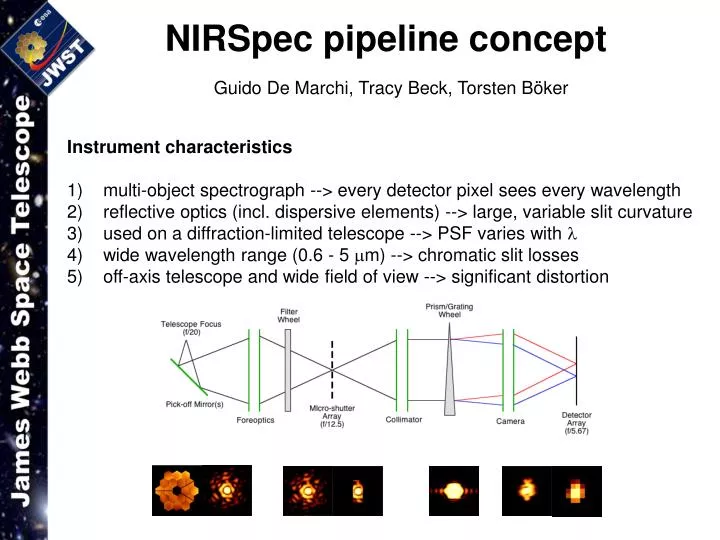
NIRSpec pipeline conceptGuido De Marchi, Tracy Beck, Torsten Böker Instrument characteristics multi-object spectrograph --> every detector pixel sees every wavelength reflective optics (incl. dispersive elements) --> large, variable slit curvature used on a diffraction-limited telescope --> PSF varies with l wide wavelength range (0.6 - 5 mm) --> chromatic slit losses off-axis telescope and wide field of view --> significant distortion
NIRSpec pipeline concept Active MSA area Mounting frame Fixed slits and IFU aperture Detector array Direction of dispersion
Headaches..... NIRSpec pipeline conceptGuido De Marchi, Tracy Beck, Torsten Böker Instrument characteristics multi-object spectrograph --> every detector pixel sees every wavelength reflective optics (incl. dispersive elements) --> large, variable slit curvature used on a diffraction-limited telescope --> PSF varies with l wide wavelength range (0.6 - 5 mm) --> chromatic slit losses off-axis telescope and wide field of view --> significant distortion
RAW DATA BIAS/DARK REF. FRAMES BIAS & DARK SUBTRACTION (Assuming no l-dependence) LINEARITY REF. FRAME LINEARITY CORR. “P-FLAT” REF. FRAME PIXEL-TO-PIXEL DQE CORR. One window for every open shutter…. LOCATE EXTR. WINDOW MSA CONFIG. & DISTORTION MAP THROUGHPUT CORRECTION (incl. L-flat, blaze function, transmission of optics, & “default” chromatic slit loss) FLATFIELD REF. CUBE GRATING EQUATION FINAL l CALIBRATION (dispersion solution) GW TELEMETRY GEOMETRIC DISTORTION (spatial) GEOMETRIC DISTORTION MAP PHOTFLAM KEYWORD ABSOLUTE FLUX CALIBRATION EXTRACT 1-D SPECTRUM SUBTRACT BACKGROUND “DELTA” CHROMATIC SLIT LOSS CORR. FINAL 1D SPECTRUM A first outline of the NIRSpec pipeline
MSA mask Red: object, green: background Extraction boxes overlap, possible “spill-over” Defining the extraction windows Each spectrum has “extraction box” on FPA
RAW DATA BIAS/DARK REF. FRAMES BIAS & DARK SUBTRACTION LINEARITY REF. FRAME LINEARITY CORR. “P-FLAT” REF. FRAME PIXEL-TO-PIXEL DQE CORR. LOCATE EXTR. WINDOW MSA CONFIG. & DISTORTION MAP THROUGHPUT CORRECTION (incl. L-flat, blaze function, transmission of optics, & “default” chromatic slit loss) FLATFIELD REF. CUBE GRATING EQUATION FINAL l CALIBRATION (dispersion solution) GW TELEMETRY GEOMETRIC DISTORTION (spatial) GEOMETRIC DISTORTION MAP PHOTFLAM KEYWORD ABSOLUTE FLUX CALIBRATION EXTRACT 1-D SPECTRUM SUBTRACT BACKGROUND “DELTA” CHROMATIC SLIT LOSS CORR. FINAL 1D SPECTRUM An outline of the NIRSpec pipeline (Assuming no l-dependence) One window for every open shutter….
Operations on the extraction windows Same as those carried out for traditional ground-based MOS • flat-field (uniformity of detector response): f(l), f(x,y) • tracing the spectrum and rectifying it: f(l), f(x,y) • wavelength calibration: f(l), f(x,y) • flux calibration (throughput of optics and gratings): f(l), f(x,y) • absolute flux calibration But wait… Because of NIRSpec’s design (e.g. MSA always in the way), some of the steps above must be carried out simultaneously, require calibration measurements that are intertwined
^ Throughput correction of y ---> l ---> x ---> “Flat-fielding” NIRSpec spectra Need a “throughput” data cube (for each filter/grating combination) Output (assuming a source with flat spectrum) l ---> l ---> Goal: to correct for the total instrumental throughput variations, both as a function of wavelength (e.g. optics transmission, blaze function) and field angle (e.g. DQE, vignetting).
Contributions to the “Throughput correction” • reflectivity of all mirrors: f(l), f(x,y) • transmission curves of filters: f(l) • blaze function of gratings: f(l), f(x,y) • large-scale response of detector (L-flat): f(l), f(x,y) • All contributions are measured at component level, and built into a physical/optical instrument model. Once NIRSpec is assembled, they cannot be measured individually. However, once a shutter has been specified, all of them are - in principle - deterministic, and can be accurately modeled. Using the instrument model, all these effects will be corrected simultaneously. But wait……
1 mm 3 mm 5 mm The bummer: chromatic slit loss Fixed slit size, but variable PSF width……. …… causes “flaring” and intensity gradient: A “default” correction for e.g. a perfectly centered point source can be included in throughput correction. The user needs to optimize this correction later….. l --->
RAW DATA BIAS/DARK REF. FRAMES BIAS & DARK SUBTRACTION LINEARITY REF. FRAME LINEARITY CORR. “P-FLAT” REF. FRAME PIXEL-TO-PIXEL DQE CORR. LOCATE EXTR. WINDOW MSA CONFIG. & DISTORTION MAP THROUGHPUT CORRECTION (incl. L-flat, blaze function, transmission of optics, & “default” chromatic slit loss) FLATFIELD REF. CUBE GRATING EQUATION FINAL l CALIBRATION (dispersion solution) GW TELEMETRY GEOMETRIC DISTORTION (spatial) GEOMETRIC DISTORTION MAP (output is re-sampled grid) PHOTFLAM KEYWORD ABSOLUTE FLUX CALIBRATION EXTRACT 1-D SPECTRUM SUBTRACT BACKGROUND “DELTA” CHROMATIC SLIT LOSS CORR. FINAL 1D SPECTRUM An outline of the NIRSpec pipeline (Assuming no l-dependence) One window for every open shutter….
l1 l2 li Rectifying NIRSpec Spectra Slit is curved (function of field angle) Lines of constant l spread over multiple pixel columns l1 l2 li Use “Drizzle” technique as possible approach for coordinate transform Need rebinning before final spectrum is extracted
l1 l2 li “Delta” correction for chromatic slit loss • - depends on source shape and position within shutter • must be user-controlled l1 l2 li • Collapse to 1-d spectrum • - depends on source extent and background subtraction • must be user-controlled For quick-look analysis, pipeline subtracts TBD “default” background
RAW DATA BIAS/DARK REF. FRAMES BIAS & DARK SUBTRACTION LINEARITY REF. FRAME LINEARITY CORR. “P-FLAT” REF. FRAME PIXEL-TO-PIXEL DQE CORR. LOCATE EXTR. WINDOW MSA CONFIG. & DISTORTION MAP THROUGHPUT CORRECTION (incl. L-flat, blaze function, transmission of optics, & “default” chromatic slit loss) FLATFIELD REF. CUBE GRATING EQUATION FINAL l CALIBRATION (dispersion solution) GW TELEMETRY GEOMETRIC DISTORTION (spatial) GEOMETRIC DISTORTION MAP PHOTFLAM KEYWORD ABSOLUTE FLUX CALIBRATION EXTRACT 1-D SPECTRUM SUBTRACT BACKGROUND “DELTA” CHROMATIC SLIT LOSS CORR. FINAL 1D SPECTRUM An outline of the NIRSpec pipeline “CALWEBB” (Assuming no l-dependence) (one window for every open shutter…. ) (output is re-sampled grid) “CALNIRSpecA” (one spectrum for every open shutter) “CALNIRSpecB” (defined by user or average) (defined by user) (erg/cm2/s/Å, sampled within variable slit aperture)