Download
1 / 19
190 likes | 198 Vues
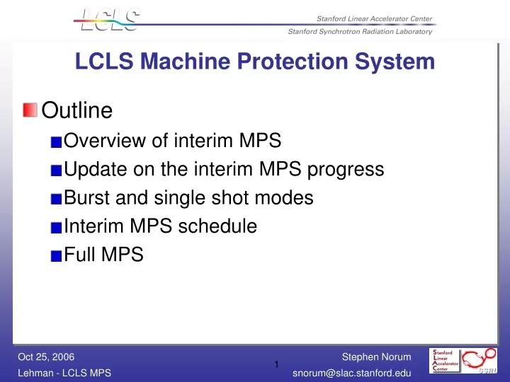
LCLS Machine Protection System. Outline Overview of interim MPS Update on the interim MPS progress Burst and single shot modes Interim MPS schedule Full MPS. Overview of Interim MPS. Using existing infrastructure (1553 MPS) Adding new signals and devices

E N D
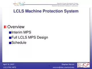
LCLS Machine Protection System • Outline • Overview of interim MPS • Update on the interim MPS progress • Burst and single shot modes • Interim MPS schedule • Full MPS
Overview of Interim MPS • Using existing infrastructure (1553 MPS) • Adding new signals and devices • Interim MPS will be used for gating beam • Single Shot Mode • Burst Mode • MPS algorithm is responsible for both LCLS and CID beam • Pockels cell and MPS mechanical shutter limit laser rate on cathode
1553 MPS • MPS device faults are input to Latching Digital Input Modules (LDIMs) • Algorithms running in local processors (APs) determine the max allowed rate based on these faults • The supervisor (SP00) chooses the lowest rate from the APs for the beam’s max allowed rate
Status • LDIM Assignments and MPS Database • LDIM channels have been assigned • VMS database has been built from these assignments • Algorithm • Algorithm processor code is near completion and is being reviewed
Interim MPS Devices • Vacuum valves/status • Beam stoppers • Magnet power supplies • Profile monitors • Standalone toroid, toroid comparators • Flow switches and temperature monitors • Joule meter • Tone interrupt unit (TIU) • Protection Ion Chambers (PICs)
Interesting Additions • MPS responsible for both CID and LCLS beam • BAS II stoppers are used to isolate LCLS • While BAS II stoppers are in • TIU is ignored as there are no devices between BX01 and TD11 • Algorithm rate limits LCLS beam only • While BAS II stoppers are out • TIU works regularly—will zero rate all beams on any TIU fault • Algorithm rate limits both CID and LCLS beam • Algorithm switches modes automatically
Interesting Additions • Burst and Single Shot Modes • Required for profile monitor acquisition • Burst mode—create a specified number of pulses at a requested rate • Single shot—create a single pulse • Both modes are preceded and followed by no beam
Burst Mode • Implementation • EPICS IOC obtains three pieces of information • Number of pulses in burst • Burst Mode—a request to go enter burst mode • Burst Request—the request to allow beam • An event receiver (EVR) provides timing data to IOC • IOC uses the timing data to count pulses • When number of requested pulses have been created, the IOC drops the burst request • Timing is handled by IOC, rate limiting logic is handled by MPS algorithm
Single Shot Mode • Implementation similar to Burst Mode • “Counting” is done in hardware • A hardware flip-flop is set when single shot mode is requested • When the single shot request is made, a pulse is created • The trigger for this pulse clears the flip-flop, ensuring only one pulse is created
Full MPS Requirements • Strict timing requirement—respond to MPS faults before next 120 Hz pulse (8.3 ms) • Multiple rate limits determined by fault location • Automatic Recovery—if requested, raise beam to before-fault rate after a fault is corrected • Fault logic based on how quickly an integrated loss threshold is exceeded
Simplified MPS Device Layout (Note: Only PICs and PLICs shown. Many more devices are input to the MPS)
Full LCLS MPS • New hardware developed by MRF • Modified VME-EVR-200 (VME-EVR-235) • Larger FPGA (XC2VP20) • 2× logic cells, 1.5× IO, 2× PPC cores • Additional SFP transceiver and clock circuit • 10/100 MAC/PHY • MMC Slot for Atmel Flash Card • 128 MB SDRAM • Board has been shipped
VME-EVR-235 Micro-Research Finland Oy
Full LCLS MPS • MPS hardware provides a high-speed communication path back to EVG (2.5 Gbps) • The MPS’s mitigation path is independent of the EVG and MPG, allowing the MPS to quickly respond to faults • Design overview has been presented to small group • Conceptual design review scheduled for November 9th