Download
1 / 29
300 likes | 592 Vues
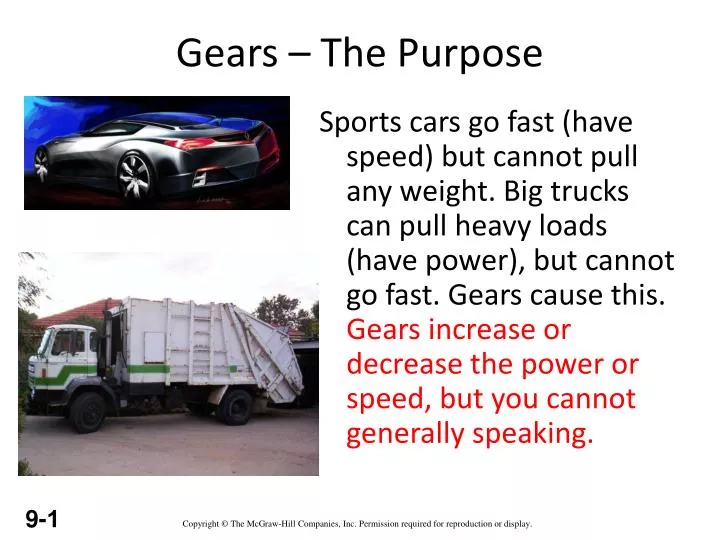
Gears – The Purpose. Sports cars go fast (have speed) but cannot pull any weight. Big trucks can pull heavy loads (have power), but cannot go fast. Gears cause this. Gears increase or decrease the power or speed, but you cannot generally speaking. Gear. Spur gears are wheels with teeth.

E N D
Gears – The Purpose Sports cars go fast (have speed) but cannot pull any weight. Big trucks can pull heavy loads (have power), but cannot go fast. Gears cause this. Gears increase or decrease the power or speed, but you cannot generally speaking.
Gear • Spur gears are wheels with teeth
Where does all this “torque” come from? Consider a pair of gears that are meshed together. F A torque on this axle... …produces a force at the tooth. T r The moment arm is the radius of the gear. Remember:T= F x r
The force from the small gear’s tooth pushes against the large gear’s tooth. This creates an equal (and opposite) force in the large gear. This is Newton’s 3rd Law. F …and produces a larger torque on this axle. r T The force acts through this larger moment arm...
F1 = -F2 T1 r2 r1 T2 T1 = F1 x r1 T2 = F2 x r2 Analyzing the forces... • F1 = T1 / r1 • F2 = T2 / r2 • F1 = - F2 • T1 / r1 = -T2 / r2 • -T2 / T1= r2 / r1 The ratio of torques is the ratio of the gear radii. This is the gear ratio!
Gear Systems An ‘idler’ gear is another important gear. In the example opposite gear ‘A’ turns in an anticlockwise direction and also gear ‘C’ turns in an anticlockwise direction. The ‘idler’ gear is used so that the rotation of the two important gears is the same.
Idler Gear • Recall that when using spur gears, the output axle rotates in the opposite direction as the input axle. • You can also use idler gears to change the spacing between the input and output axles • Remember, idler gears do not change the gear ratio
Drawing Gears It would be very difficult to draw gears if you had to draw all the teeth every time you wanted to design a gear system. For this reason a gear can be represented by drawing two circles. CIRCLES OVERLAP WHERE TEETH MESH
Gear train This is a good example of a ‘gear train’. A gear train is usually made up of two or more gears. The driver in this example is gear ‘A’. If a motor turns gear ‘A’ in an anticlockwise direction; Which direction does gear ‘B’ turn ?Which direction does gear ‘C’’ turn ? Counter-ClockwiseDoes gear ‘C’ revolve faster or slower than gear ’A ? - explain your answer.’ Clockwise SLOWER – SMALLER GEAR TURNS A LARGER GEAR
GEAR TRAINS • A gear train is two or more gear working together by meshing their teeth and turning each other in a system to generate power and speed • It reduces speed and increases torque • Electric motors are used with the gear systems to reduce the speed and increase the torque
Types of Gear Trains • Simple gear train • Compound gear train • Planetary gear train Simple Gear Train • The most common of the gear train is the gear pair connecting parallel shafts. The teeth of this type can be spur, helical or herringbone. • Only one gear may rotate about a single axis
Simple Gear Trains The typical spur gears as shown in diagram. The direction of rotation is reversed from one gear to another. The only function of the idler gear is to change the direction of rotation.
Simple Gear Trains The velocity v of any point on the circle must be the same for all the gears, otherwise they would be slipping.
Torque & Efficiency The power transmitted by a torque T N-m applied to a shaft rotating at n rev/min is given by: In an ideal gear box, the input and output powers are the same so;
Torque & Efficiency It follows that if the speed is reduced, the torque is increased and vice versa. In a real gear box, power is lost through friction and the power output is smaller than the power input. The efficiency is defined as: Because the torque in and out is different, a gear box has to be clamped in order to stop the case or body rotating. A holding torque T3 must be applied to the body through the clamps.
Torque & Efficiency holding torque. The amount of torque required for a motor to remain in a fixed position The total torque must add up to zero. T1 + T2 + T3 = 0 If we use a convention that anti-clockwise is positive and clockwise is negative we can determine the holding torque. The direction of rotation of the output shaft depends on the design of the gear box.
Problem 1 A gear box has an input speed of 1500 rev/min clockwise and an output speed of 300 rev/min anticlockwise. The input power is 20 kW and the efficiency is 70%. Determine the following. i. The gear ratio; ii. The input torque.; iii. The output power.; iv. The output torque; v. The holding torque. Dr.T.V.Govindaraju,SSEC
Compound Gear Train • For large velocities, compound arrangement is preferred • Two or more gears may rotate about a single axis
Compound gears are used in engines, workshop machines and in many other mechanical devices. In the diagram, gear ‘A’ is actually two gears attached to each other and they rotate around the same centre. Sometimes compound gears are used so that the final gear in a gear train rotates at the correct speed.
Reverted Gear train Concentric input & output shafts
Reverted Gear train The driver and driven axes lies on the same line. These are used in speed reducers, clocks and machine tools. If R and N=Pitch circle radius & number of teeth of the gear RA + RB = RC + RD and NA + NB = NC + ND