Download
1 / 28
280 likes | 444 Vues
Evaluating a QTH for Contesting and DXing. Steve London, N2IC. Factors to be considered. Site Selection Criteria Ionospheric propagation to maximize QSO’s and multipliers Relative rarity – country, state, prefix … Antenna-friendly government and neighbors Antenna-friendly environment

E N D
Evaluating a QTH for Contesting and DXing Steve London, N2IC
Factors to be considered • Site Selection Criteria • Ionospheric propagation to maximize QSO’s and multipliers • Relative rarity – country, state, prefix … • Antenna-friendly government and neighbors • Antenna-friendly environment • Cost of living and land • Accessibility • Availability and cost of resources for assembling station • Quiet receiving location • Proximity to non-contesting amenities and employment • Do you really want to live there ?
Evaluating the location • What are the propagation characteristics to the desired targets ? • What is the effect of local topography ? • Is there an optimal, realizable antenna system for the location ?
How High is that Mountain ? 4.6 degree horizon (tan-1 h/d) DeLorme TopoUSA
What about the curvature of the earth ? H = D2/1.47727 H = Number of feet that object “drops” D = Number of miles from object For D Less than 15 miles, earth curvature doesn't matter
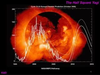
Case Study • Denver-to-JA/UA0/JT • 15 meters • 0100Z • March 30 • Sunspot Number = 70 (Solar Flux = 120)
Summary of Steps • Model the terrain from your QTH in the interesting directions • Model your antennas over your terrain • Model the propagation to your target • Compare the propagation to your target with "real" terrain and "real“ antennas vs. "ideal" terrain and "ideal" antennas.
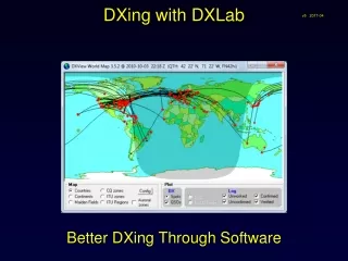
Model the Terrain • Paper USGS Topographic Maps • Draw a line from the tower base in the direction of interest • Plot and read points along the line • Painstaking ! • Topographic Map Software (i.e. DeLorme TopoUSA) • Easier, but still doesn’t automatically generate data • MicroDEM (Internet Freeware and included in ARRL Antenna Book) • Manipulates Digital Elevation Model (DEM) topographic data available free on the internet. • Automatically generates azimuth terrain profile files
Model the Antenna over Flat Terrain ARRL HFTA
Model the Propagation 2-hop F2 Transition 3-hop F2 VOACAP
Put it all together ! 4.6 degree horizon, 50 foot high monobander over flat terrain VOACAP
1 degree horizon, 50 foot high monobander over flat terrain VOACAP
Conclusions • Difficult to make sweeping statements based on 1 case study • This single case study would suggest: - The 4.6 % obstruction significantly degrades performance to areas with marginal openings.
Useful References • Propagation prediction software: • VOACAP http://elbert.its.bldrdoc.gov/hf.html • VOACAP Quick Guide - OH6BG http://www.uwasa.fi/~jpe/voacap/ • MultiNEC (http://www.qsl.net/ac6la) • ACE-HF (Reviewed Nov 2002 QST) • PropMan2000 (Sept 2001 QST) • WinCAP (Jan 2003 QST) • Topographic map software: • DeLorme TopoUSA - http://www.delorme.com/topousa/default.asp • MicroDEM – http://www.nadn.navy.mil/Users/oceano/pguth/website/microdem.htm • Terrain analysis software: • HFTA (HF Terrain Analysis) – ARRL Antenna Book, 20th edition,
What I Have Learned at the New QTH • It’s easy to be moderately strong • 30’ of height works well on the high bands • Not so easy to be REALLY strong • Stacked yagis play predictably on flat terrain • No apparent stacking gain on a mountain • Antenna and terrain modeling doesn’t tell the whole story • HFTA has significant issues with complex terrain