Download

1 / 54
550 likes | 668 Vues
Hardware/Software Codesign of Embedded Systems. SYSTEM MODELS. Voicu Groza SITE Hall, Room 5017 562 5800 ext. 2159 Groza@SITE.uOttawa.ca. SPECIFICATIONS. After Peter Marwedel, Univ. Dortmund, Germany. Specifications. After Peter Marwedel, Univ. Dortmund, Germany.

E N D
Hardware/Software Codesign of Embedded Systems SYSTEM MODELS Voicu Groza SITE Hall, Room 5017 562 5800 ext. 2159 Groza@SITE.uOttawa.ca
SPECIFICATIONS After Peter Marwedel, Univ. Dortmund, Germany
Specifications After Peter Marwedel, Univ. Dortmund, Germany
Specification of embedded systems:Requirements for specification techniques (1) • HierarchyHumans not capable to understand systemscontaining more than ~5 objects.Most actual systems require more objects Hierarchy • Behavioral hierarchyExamples: states, processes, procedures. • Structural hierarchyExamples: processors, racks, printed circuit boards proc proc proc After Peter Marwedel, Univ. Dortmund, Germany
Specification of embedded systems:Requirements for specification techniques (2) • Timing behavior.State-oriented behaviorRequired for reactive systems;classical automata insufficient. • Event-handling(external or internal events) • No obstacles for efficient implementation After Peter Marwedel, Univ. Dortmund, Germany
Requirements for specification techniques (3) • Support for the design of dependable systemsUnambiguous semantics, ... • Exception-oriented behaviorNot acceptable to describe exceptions for every state. We will see, how all the arrows labeled k can be replaced by a single one. . After Peter Marwedel, Univ. Dortmund, Germany
Requirements for specification techniques (4) • ConcurrencyReal-life systems are concurrent • Synchronization and communicationComponents have to communicate! • Presence of programming elementsFor example, arithmetic operations, loops, and function calls should be available • Executability (no algebraic specification) • Support for the design of large systems ( OO) • Domain-specific support After Peter Marwedel, Univ. Dortmund, Germany
Requirements for specification techniques (5) • Readability • Portability and flexibility • TerminationIt should be clear, at which time all computations are completed • Support for non-standard I/O devicesDirect access to switches, displays, ... • Non-functional propertiesfault-tolerance,disposability, EMC-properties, weight, size, user friendliness, extendibility, expected life time, power consumption... • Adequate model of computation After Peter Marwedel, Univ. Dortmund, Germany
Models of computation- Definition - • Models of computation define: • Components and an execution model for computations for each component • Communication model for exchange of information between components. Message passing? Rendez-vous? • See also • Work by Ed Lee, UCB • Axel Jantsch: Modeling Embedded Systems and Soc's: Concurrency and Time in Models of Computation, Morgan-Kaufman, 2004 After Peter Marwedel, Univ. Dortmund, Germany
Von Neumann model Sequential execution, program memory etc. a:=5 b:=7 c:=8 a:=6 a:=9 Components (1) • Discrete event model queue 5 6 a b c time action 5 10 13 15 19 7 8 After Peter Marwedel, Univ. Dortmund, Germany
Components (2) • Finite state machines • Differential equations After Peter Marwedel, Univ. Dortmund, Germany
Communication • Shared memory • Asynchronous message passing Comp-1 memory Comp-2 • Message passingTransmission of messages over channels • Synchronous message passing After Peter Marwedel, Univ. Dortmund, Germany
Combined models- languages presented later in this chapter - • SDL (Synchronous data Flow, 1987)FSM+synchronous message passing • StateChartsFSM+shared memory • CSP (Communicating Sequential Processes – Hoare, 1985), ADAvon Neumann execution+synchronous message passing • …. After Peter Marwedel, Univ. Dortmund, Germany
Problems with thread-based concurrency • “Even the core … notion of “computable” is at odds with the requirements of embedded software. In this notion, useful computation terminates, but termination is undecidable. In embedded software, termination is failure, and yet to get predictable timing, subcomputations must decidably terminate. • The lack of timing in the core abstraction is a flaw, from the perspective of embedded software, and threads as a concurrency model are a poor match for embedded systems. … they work well only … where best-effort scheduling policies are sufficient. • What is needed is nearly a reinvention of computer science.” Ed Lee: Absolutely Positively on Time, IEEE Computer, July, 2005 Search for non-thread-based, non-von-Neumann MoCs After Peter Marwedel, Univ. Dortmund, Germany Ptolemy simulations
Ptolemy • Ptolemy (UC Berkeley) is an environment for simulating multiple models of computation. http://ptolemy.berkeley.edu/ Available examples are restricted to a subset of the supported models of computation. After Peter Marwedel, Univ. Dortmund, Germany
Facing reality • No language that meets all language requirements using compromises After Peter Marwedel, Univ. Dortmund, Germany
CONCEPTUAL MODELS • System Specification Models • Finite State Machines (FSM) • Algorithmic State Machines (ASM) • Non-deterministic FSM (NDFSM) • Extended FSM • Codesign FSM
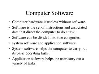
System Specification Models • Formal system consisting of objects & composition rules, used for describing a system’s characteristics • A model provides: • clear and unambiguous description of the system function • documentation of the initial design process • no constraints to the implementation • easy application of Computer Aided Design (design space exploration, partitioning, synthesis, validation, testing) • A model has to be • complete • comprehensible to designers (natural)
Models and Architectures Highest level of abstraction of a system: • Model = conceptual view = how a system works DESIGN PROCESS designers describe the system functionality in a language that is most appropriate for the model • Architecture = implementation view = how a system will be manufactured
System Specification Models * Distinguish between models and languages (a language implies one or more models) * Main models for embedded systems: • State-oriented (Petri Nets, Finite State Machines) • Activity-oriented (data-flow graph, flow-charts) • Structure-oriented • Data-oriented • Heterogeneous (control/data flow graph, OO, queuing)
System Specification Models * Model choice depends on: - Application domain, e.g., • data flow for digital signal processing, • finite state machines for control, • simulation engine for hardware, ... * Language choice depends on: - Available tools - Personal taste and/or company policy - Underlying model (the language must have a semantics in the chosen model)
Control versus Data Flow * Fuzzy distinction, yet useful for: - specification (language, model, ...) - synthesis (scheduling, optimization, ...) - validation (simulation, formal verification, ...) * Rough classification: - control: - don't know when data arrive (quick reaction) - time of arrival often matters more than value - data: - data arrive in regular streams (samples) - value matters most
Control versus Data Flow * Specification, synthesis and validation methods emphasize: - for control: - event/reaction relation - response time (Real Time scheduling for deadline satisfaction) - priority among events and processes - for data: - functional dependency between input and output - memory/time efficiency (data flow scheduling for efficient pipelining) - all events and processes are equal
Finite State Machines • Functional decomposition into states of operation • Inputs and outputs are sequences of events • Typical domains of application: - control functions - protocols (telecom, computers, ...) * Different communication mechanisms: - synchronous (classical FSMs, Moore, Mealy) - asynchronous (Communicating Sequential Process - CSP, Hoare `85)
The termSynchronous … … has been used in the literature to mean at least three rather different concepts: 1. ``Clocked'', describing a system where all the components are synchronized by a global signal, as opposed to asynchronous systems where synchronization is a local property. 2. ``Zero reaction time'', describing a system where the components react instantaneously to an event. 3. ``Without acknowledge'', describing a communication protocol where the sender does not wait for the receiver to acknowledge the reception of the message. In the following, we will use the first meaning, unless explicitly noted (for example the expression ``synchronous programming language'' refers to the second meaning).
Recap of classical automata • Classical automata: input X Internal state Z output Y clock Moore + Mealy automata=finite state machines (FSMs) Next state Z+ computed by function Output computed by function e=1 Z0 Z1 • Moore-automata:Y = (Z); Z+ = (X, Z) • Mealy-automataY = (X, Z); Z+ = (X, Z) 0 1 e=1 e=1 Z3 Z2 2 3 e=1
FSM Example * Informal specification: If the driver turns on the key, and does not fasten the seat belt within 5 seconds then an alarm beeps for 5 seconds, or until the driver fastens the seat belt, or until the driver turns off the key
FSM ExampleState Diagram KEY_ON=>START_TIMER WAIT (KEY_OFF or BELT_ON) => OFF END_TIMER_5 => ALARM_ON (BELT_ON or END_TIMER_10 or KEY_OFF) => ALARM_OFF ALARM If no condition is satisfied, implicit self-loop in the current state
FSM Definition • FSM = (I, O, S, S0, , ) previous notation(X,Y, Z, X0, , ) - I = { KEY_ON, KEY_OFF, BELT_ON, END_TIMER_5, END_TIMER_10 } - O = { START_TIMER, ALARM_ON, ALARM_OFF } - S = { OFF, WAIT, ALARM } - S0 = OFF - : 2I × S -> S e.g. ({KEY_OFF}, WAIT) = OFF - : 2I × S -> 2O e.g. ({KEY_ON}, OFF) = {START_TIMER} Set of all subsets of I (implicit ``and'') All other inputs are implicitly absent
I N P U T S O U T P U T S NEXT STATE PRESENT STATE START_TIMER END_TIMER_10 END_TIMER_5 ALARM_OFF KEY_ON ALARM_ON KEY_OFF BELT_ON OFF 1 x x x x WAIT 0 0 1 OFF 0 x x x x OFF 0 0 0 WAIT x 1 x 0 x OFF 0 0 0 WAIT x x 1 0 x OFF 0 0 0 WAIT x x x 1 x ALARM 0 1 0 WAIT x 0 0 0 x WAIT 0 0 0 ALARM x x 1 x x OFF 1 0 0 ALARM x x x x 1 OFF 1 0 0 ALARM x 1 x x x OFF 1 0 0 ALARM x 0 0 x 0 ALARM 0 0 0 Symbolic State Transition Table
Architecture used in a register level implementation START_TIMER KEY_ON ...... END_TIMER_10 ALARM_ON Combinational Logic State register
Register Level Implementation Architecture of Mealy FSM KEY_ON END_TIMER_10 • • • State register • • • START_TIMER : 2I × S -> S : 2I × S -> 2O ALARM_ON Combinational Logic
Register Level Implementation Architecture of Moore FSM KEY_ON END_TIMER_10 State register • • • START_TIMER : 2I × S -> S : S -> 2O ALARM_ON Combinational Logic
Algorithmic State Machine (ASM) • The following are the major steps in the ASM methodology: • Create an algorithm, using pseudocode, to describe the desired operation of the device • Convert the pseudocode into an ASM chart (the basic brick = ASM block) • Design the datapath based on the ASM chart • Create a detailed ASM chart based on the datapath • Design the control logic based on the detailed ASM chart • Combination of datapath and control logic makes up the actual logic system that will solves the original problem.
T F ASM Example
Non-deterministic FSM(NDFSM) * and may be relations instead of functions: - 2I × S × S e.g. ({KEY_OFF, END_TIMER_5}, WAIT) = {{OFF}, {ALARM}} - 2I × S × 2O * Nondeterminism can be used to describe: - an unspecified behavior (incomplete specification) - an unknown behavior (environment modeling) implicit ``and'’ implicit ``or''
BIT or BIT=> BIT or BIT=> BIT or BIT=> BIT=> ERR BIT=> BIT=> BIT=> BIT=> BIT or BIT=>ERR NDFSM: incomplete specification • E.g. Error checking first partially specified: ... 0 1 7 8 SYNC => • Then completed as even parity: ... p7 p1 BIT=> BIT => ERR ... BIT=> 0 d1 d7 BIT=> 8 BIT=> SYNC => • Could be implemented as CRC later
NDFSM: unknown behavior • * Modeling the environment • * Useful to: • - optimize (don't care conditions) • - verify (exclude impossible cases) • * E.g. driver model: • * Can be refined • E.g. introduce timing constraints • (minimum reaction time 0.1 s) => KEY_ON or KEY_OFF or BELT_ON s0
NDFSM: time range * Special case of unspecified/unknown behavior, but so common to deserve special treatment for efficiency * E.g. undetermined delay between 6 and 10 s SEC=> SEC=> SEC=> 1 START=> 2 3 4 SEC=> START=> SEC=>END 5 0 9 SEC => END SEC=> END SEC=> SEC=> END 6 SEC=> 8 7 SEC=> SEC=>
NDFSMs and FSMs * Formally FSMs and NDFSMs are equivalent * In practice, NDFSMs are often more compact (exponential blowup for determinization) s1 c c a s1 c c b a a s1,s3 s2,s3 s3 a b b a s2 s3 a a s2
I = I0U I1 O FSM E I1 O’ O U O’ O FSM Composition E = {S, S0, I, O, T} and M = {S’, S’0, I’, O’, T’} The composition of E and M, denoted E || M, can be defined by a partition I = I0U I1 of the inputs of the first machine E and a partition O’ = O’0U O’1 of the outputs of the second machine M, such that I1 = O’1 and O = I’. Additionally, I0 must be disjoint from O’. The new FSM, E || M, can be defined as follows: —set of states, S X S’; —input variables, I0, —output variables O U O’, —initial states, S0 X S’0, —transition relation T|| O’1 = I1
FSM Composition * Bridle complexity via hierarchy: FSM product yields an FSM * Fundamental hypothesis: all the FSMs change state together (synchronicity) * System state = Cartesian product of component states (state explosion may be a problem...) * E.g. seat belt control + timer SEC => SEC => SEC => START_TIMER => 1 3 4 2 SEC => END_5_SEC START_TIMER => SEC => SEC => SEC => SEC => 0 8 7 6 5 9 SEC => END_5_SEC
OFF, 0 WAIT, 1 SEC and (KEY_OFF or BELT_ON) => SEC and (KEY_OFF or BELT_ON) => WAIT, 2 FSM Composition KEY_ON and START_TIMER => START_TIMER OFF, 1 SEC and (KEY_OFF or BELT_ON) => Etc., etc., OFF, 2
FSM Composition • Given • M1 = (I1, O1, S1, r1, 1, 1) • M2 = (I2, O2, S2, r2, 2, 2) • Find the composition M= (I, O, S, r, , ) • given a set of constraints of the form C = {(o, i1, i2, , ..., in) : o is connected to i1, i2,, ..., in}
I’2 I’2 I”2 1 2 I1 I”2 • Given • M1 = (I1, O1, S1, r1, 1, 1) • M2 = (I2, O2, S2, r2, 2, 2) • Find the composition M= (I, O, S, r, , ) • given a set of constraints of the form I2 = I’2 U I”2 C = {O1 is connected to I”2}
FSM Composition * product of FSM1 and FSM2 * I = I1 I’2 * O = O1 O2 * Assume e.g. that o1 I2, o1 O1 (communication) * S = S1 × S2 * and are such that, e.g., for each pair: - 1 ({i1}, s1) = t1, 1({i1}, s1) = {o1} - 2({i2, o1}, s2) = t2, 2({i2}, s2) = {o2} we have: - ({ i1, i2, o1}, (s1, s2)) = (t1, t2), - ({ i1, i2, o1}, (s1, s2)) = {o1, o2}
FSM Composition Unconditional product M’=(I’,O’,S’,r’, ’, ’) I’= I1I2 O’= O1 O2 S’= S1 S2 ’= {(A1, A2, s1, s2, t1, t2):(A1, s1, t1) 1 & (A2, s2, t2) 2} ’= {(A1, A2, s1, s2, B1, B2):(A1, s1, B1) 1 & (A2, s2, B2) 2} Note: A1 I1, A2 I2 , B1 O1, B2 O2 2XY 2X x 2Y Constraint application = {(A1, A2, s1, s2, B1, B2) ’: for all (o, i1, i2, , ..., in) C o B1 B2 = if and only if ij A1 A2 for all j} The application of the constraint rules out the cases where the connected input and output have different values.
FSM Composition Problem: what if there is a cycle? • Moore machine: depends on input and state, only on state • composition is always well defined • Mealy machine: and depend on input and state • composition may be undefined • What if 1({i1},s1)={o1} but o22({i2},s2)? o2 i1 o1 i2 FSM2 FSM1
Summary of Finite State Machines Car OR 5min • * Advantages: • - Easy to use (graphical languages) • - Powerful algorithms for • - synthesis (SW and HW) • - verification • * Disadvantages: • - Sometimes over-specify implementation • (sequencing is fully specified) • - Numerical computations cannot be specified • compactly • (need extended FSMs) HG HY 10sec 10sec SY SG 30sec
S1 Extended FSM with a Datapath (FSMD) • Define • a set of storage variables VAR • a set of expressions EXP = {f(x,y,z,…) | x,y,z,…VAR} • a set of storage assignments A = {X e | X VAR, e EXP} • A set of status expressions STAT = {Rel(a,b) | a,b EXP} • FSMD defined as the quintuple < S, I STAT, O A, f, h > Where: f: S x(I STAT) S h: S x(I STAT) O A (curr_floor = req_floor) / output := 0 start (curr_floor != req_floor) / output:= curr_floor - req_floor; curr_floor := req_floor