Download
1 / 1
10 likes | 188 Vues
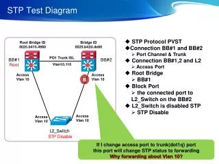
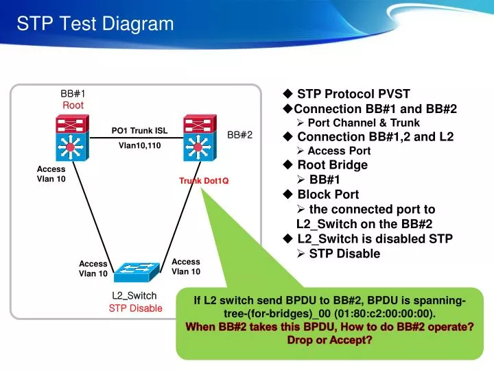
STP Test Diagram. STP Protocol PVST Connection BB#1 and BB#2 Port Channel & Trunk Connection BB#1,2 and L2 Access Port Root Bridge BB#1 Block Port the connected port to L2_Switch on the BB#2 L2_Switch is disabled STP STP Disable. BB#1 Root. PO1 Trunk ISL Vlan10,110. BB#2.

E N D
STP Test Diagram • STP Protocol PVST • Connection BB#1 and BB#2 • Port Channel & Trunk • Connection BB#1,2 and L2 • Access Port • Root Bridge • BB#1 • Block Port • the connected port to L2_Switch on the BB#2 • L2_Switch is disabled STP • STP Disable BB#1 Root PO1 Trunk ISL Vlan10,110 BB#2 Access Vlan 10 Trunk Dot1Q Access Vlan 10 Access Vlan 10 L2_Switch If L2 switch send BPDU to BB#2, BPDU is spanning-tree-(for-bridges)_00 (01:80:c2:00:00:00). When BB#2 takes this BPDU, How to do BB#2 operate? Drop or Accept? STP Disable