Download

1 / 15
170 likes | 288 Vues
Islanding Detection can be classified into passive methods, which look for events on the grid, and active methods, testing the network from the inverter or the grid distribution point. There are also methods that the utility can use to detect the conditions that would deliberately upset those conditions in order to power down the inverters.

E N D
Islanding Detection Methods subtitle
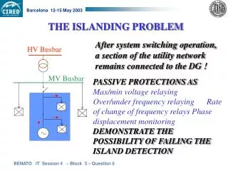
Islanding Detection Methods • These can be classified into passive methods, which look for events on the grid, and active methods, testing the network from the inverter or the grid distribution point. There are also methods that the utility can use to detect the conditions that would deliberately upset those conditions in order to power down the inverters. These methods are summarized below.
Passive and Active Methods • Passive methods include any system that detects anomalies to usual network condition, indicating the need to disconnect. • Active methods attempt to detect a network failure by injecting small signals into the line, and then detecting whether or not the signal reading changes.
Under/Over Voltage • Under/over voltage detection is normally simple to implement in mains connected inverters, because the basic function of the inverter is to mimic the grid conditions, including voltage. That means that all mains connected inverters have the hardware required to detect the changes. All that is needed is a program to detect sudden changes. However, sudden changes in voltage are common on the grid as high loads are attached and removed, so a limit must be used to avoid nuisance tripping.
Under/Over Frequency • The frequency of the power to the grid is critical to the functionality of any mains powered devices, as all inductive loads are calibrated to run at a nominal frequency of 50 Hertz. • Over and under frequency conditions can cause circulating overcurrent faults between sources of supply, leading to equipment damage and injury from overheating and possible fires. • Unlike variations in voltage, it is unlikely that a random circuit would have a frequency the same as the grid. Most modern generating devices and inverters sync to the network frequency.
Rate of Change of Frequency Rate of change of frequency is given by the following expression: where: f is the system frequency, t is the time, ∆P is the power imbalance, G is the system capacity, and H is the system inertia. If the rate of change of frequency, or ROCOF value, becomes greater than a certain value, the embedded generation will disconnect from the network.
Voltage Phase Jump Detection • Loads generally have power factors that are lagging, meaning that they do not accept the voltage from the grid perfectly, but impede it slightly. Grid-tie inverters are usually set to have power factors of unity. This will change in phase when the network fails, which we can use to detect islanding. • Inverters track the phase of the grid by tracking when the signal crosses zero volts, varying the current output to the circuit to produce the proper voltage waveform. When the grid disconnects, the power factor suddenly shifts from the grid’s unity compared to the load’s not quite unity. As the circuit is still driving a current that would produce a smooth voltage output given the known loads, this will result in a sudden change in voltage. By the time the waveform is completed and returns to zero, it will be out of phase.
Harmonics Detection • Even with noisy sources, the total harmonic distortion (THD) of a grid-tied circuit is generally immeasurable due to the practically infinite capacity of the grid that filters these events out. Inverters though, generally have much larger distortions, as much as 5% THD. This is due to their construction; some THD is a side-effect of the switched-mode power supply circuits most inverters are based on. • So when the grid disconnects, the THD of the local circuit will increase to that of the inverters themselves. This provides a very secure method of detecting islanding, because there are generally no other sources of THD that would equal the inverter. Also, interactions within the inverters, notably the transformers, have non-linear effects that produce unique 2nd and 3rd harmonics that are easily measured.
Negative-Sequence Current Injection • This is an active islanding detection method which can be used by three-phase inverters. The method is based on injecting a negative-sequence current and detecting and quantifying the corresponding negative-sequence voltage at the point of common coupling. The negative-sequence current injection method: • detects an islanding event within 60 ms (3 cycles) • requires 2% to 3% negative-sequence current injection for islanding detection; • can correctly detect an islanding event for the grid short circuit ratio of 2 or higher
Impedance Measurement • Impedance Measurement measures the overall impedance of the circuit being fed by the inverter. It does this by slightly increasing the current amplitude, presenting too much current at a given time. Usually this would have no effect on the measured voltage, as the extra current is soaked up by the grid. In the event of a disconnection, even the small increase would result in a noticeable rise in voltage, allowing detection of the island. • The main advantage of this method is that it has a very small NDZ for any given single inverter. However, in the case of multiple inverters, each one would be increasing a slightly different signal into the line, hiding the effects on any one inverter. It is possible to address this problem by communication between the inverters to ensure they all increase on the same schedule.
Slip Mode Frequency Shift • This is one of the newest methods of islanding detection. It is based on changing the phase of the inverter’s output to be slightly mis-aligned with the grid, with the expectation that the grid will overwhelm this signal. The system relies on the actions of a finely tuned phase-locked loop to become unstable when the grid does not overwhelm the signal; in this case, the PLL attempts to adjust the signal back to itself, which is programmed to continue to drift. In the case of grid loss, the system will drift away from the design frequency, causing the inverter to shut down. • The good thing is that it can be done using existing hardware that is already in the inverter. The disadvantage is that it needs the inverter to always be slightly out of sync with the grid, a lowered power factor. Generally speaking, the system has a very small NDZ and will quickly disconnect.
Frequency Bias • Frequency bias produces a slightly off-frequency signal into the grid, but resets this at the end of every cycle by jumping back into phase when the voltage passes zero. This is similar to Slip Mode, but the power factor remains closer to the grid, and resets itself every cycle. Moreover, the signal is less likely to be filtered out. • There are numerous variations to this basic scheme. The Frequency Jump version, also known as the “zebra method”, inserts forcing only on a specific number of cycles in a set pattern. This reduces the possibility that external circuits may filter out the signal.
BCJ Controls • At BCJ Controls we produce Secondary Protection Switchboards with solar protection relays for Commercial Solar over 30kW grid connections. • BCJ Controls offers excellent services and quality instrument in Electric Power Grid. Such as, testing and commissioning, installation and quality products like protection relay. Good Quality we offer to our valued customer in Australia.
BCJ Controls Need Specialist? Testing and Commissioning Products? High Quality? Contact us: (02) 9534 8465 2,17 Lorraine St PeakhurstNSW 2210
Visit us for more about Islanding: www.bcjcontrols.com.au