Download

1 / 8
80 likes | 235 Vues
17A Marlen Drive w Hamilton, NJ 08691 w USA Tel: (609) 586-8004 w Fax: (609) 586-0002 www.ippe.com. Please click on our logo or any link in this presentation to be redirected to our website & email. Thank You!. Introduction. Built: February 1977 Shut Down: June 2003

E N D
17A Marlen DrivewHamilton, NJ 08691wUSATel: (609) 586-8004wFax: (609) 586-0002www.ippe.com Please click on our logo or any link in this presentation to be redirected to our website & email. Thank You!
Introduction • Built: February 1977 • Shut Down: June 2003 • Capacity: 300 MTD based on 100% NA • Production: 60 % Nitric Acid • Technology: Chemico Process • Revamped: March 1990 • Documentation: Available
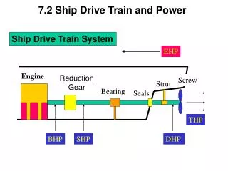
Overview Atmospheric air is filtered and compressed to about 9.5 kg/cm2. Intercooling in the air compression system is adjusted to produce hot compressed air at 232° C. Primary air, about 80% of the total compressed air passes through a compressed air filter and enters the ammonia-air mixer where air is mixed with the required amount of ammonia supplied to contractor’s battery limits at 14 kg/cm2 (min.) and 32° C. The ammonia-air mixture flows from the mixer to the burner assembly which contains a set of platinum-rhodium gauzes. The oxidation of ammonia to nitric oxide takes place at the gauze. The resulting hot gases leave the gauze at approximately 900° C and flow around the tubes of the turbine gas heater and through the tubes of the burner gas boiler, generating steam. The cooled product gases leave the boiler and flow through a catalyst recovery filter, tail gas heater, boiler feedwater heater, nitric gas cooler and water cooled weak acid condenser. Acid collected in the latter unit flows to the proper tray of the absorption tower while the uncondensed process gas flows directly to the lower part of the tower where it is mixed with air from the bleaching section. Hot secondary air from the air compression system (the remaining 20% of the compressed air) is cooled by exchange with tail gas and flows to the bottom section of the absorption tower to “bleach” the product acid before mixing with the process gas. Make-up water is pumped from the condensate tank to the top of the absorption tower, and the acid produced in the absorber passes through the bottom bleaching section where it is stripped of nitrous acid by the warm secondary air. The product acid flows to the nitric acid storage tank under system pressure. The absorption tower is designed to recover almost all the nitrogen oxides present, yielding a tail gas containing about 250 ppm by volume. The tail gas flows through the tail gas mist separator at the top of the absorption tower and then through a reheating cycle. The gas is first heated by the bleaching air in the bleach air cooler, by steam in the tail gas preheater and by exchange with the process gas in the tail gas heater and turbine gas heater. The hot tail gas then enters the power recovery turbine of the air compression system, furnishing most of the normal compression power. The remaining power required is furnished by a steam turbine.
Major Components Timeline of Replacements • November 1999 • Absorption Tower, Bottom Part Replaced (below 19th stage) • 1998 • Acid Condenser Replaced • 1997 • Chiller Compressor Installment • NH3 condenser, high receiver • Oil separator, Oil cooler etc. • March 1990 • New Air Compressor Set (inc. Expander & Steam Turbine) • Chilled Water Unit (Tank, Evaporator, (Refrigerant-NH3) etc) • NOX Abator (SCR) etc.
Major Components * A detailed and completed list of all equipment are available and to be provided on demand