Download
1 / 19
190 likes | 405 Vues
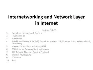
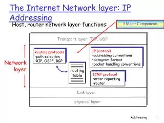
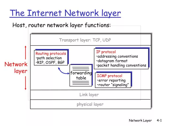
Host, router network layer functions:. ICMP protocol error reporting router “signaling”. IP protocol addressing conventions datagram format packet handling conventions. Routing protocols path selection RIP, OSPF, BGP. forwarding table. The Internet Network layer.

E N D
Host, router network layer functions: • ICMP protocol • error reporting • router “signaling” • IP protocol • addressing conventions • datagram format • packet handling conventions • Routing protocols • path selection • RIP, OSPF, BGP forwarding table The Internet Network layer Transport layer: TCP, UDP Network layer Link layer physical layer Network Layer
IP address: 32-bit identifier for host, router interface interface: connection between host/router and physical link router’s typically have multiple interfaces host may have multiple interfaces IP addresses associated with each interface 223.1.1.2 223.1.2.2 223.1.2.1 223.1.3.2 223.1.3.1 223.1.3.27 IP Addressing: introduction 223.1.1.1 223.1.2.9 223.1.1.4 223.1.1.3 223.1.1.1 = 11011111 00000001 00000001 00000001 223 1 1 1 Network Layer
IP address: network part (high order bits) host part (low order bits) What’s a network ? (from IP address perspective) device interfaces with same network part of IP address can physically reach each other without intervening router IP Addressing 223.1.1.1 223.1.2.1 223.1.1.2 223.1.2.9 223.1.1.4 223.1.2.2 223.1.1.3 223.1.3.27 LAN 223.1.3.2 223.1.3.1 network consisting of 3 IP networks (for IP addresses starting with 223, first 24 bits are network address) Network Layer
multicast address 1110 network host 110 network 10 host IP Addresses given notion of “network”, let’s re-examine IP addresses: “class-full” addressing: class 1.0.0.0 to 127.255.255.255 A network 0 host 128.0.0.0 to 191.255.255.255 B 192.0.0.0 to 223.255.255.255 C 224.0.0.0 to 239.255.255.255 D 32 bits Network Layer
IP datagram: B E A source IP addr misc fields dest IP addr data 223.1.1.1 223.1.2.1 223.1.1.2 223.1.2.9 223.1.1.4 223.1.2.2 223.1.1.3 223.1.3.27 Dest. Net. next router Nhops 223.1.1 1 223.1.3.2 223.1.3.1 223.1.2 223.1.1.4 2 223.1.3 223.1.1.4 2 Getting a datagram from source to dest. forwarding table in A • datagram remains unchanged, as it travels source to destination • addr fields of interest here Network Layer
E B A 223.1.1.1 223.1.2.1 223.1.1.2 223.1.2.9 223.1.1.4 223.1.2.2 223.1.1.3 223.1.3.27 Dest. Net. next router Nhops 223.1.1 1 223.1.3.2 223.1.3.1 223.1.2 223.1.1.4 2 223.1.3 223.1.1.4 2 Getting a datagram from source to dest. forwarding table in A misc fields data 223.1.1.1 223.1.1.3 Starting at A, send IP datagram addressed to B: • look up net. address of B in forwarding table • find B is on same net. as A • link layer will send datagram directly to B inside link-layer frame • B and A are directly connected Network Layer
E A B 223.1.1.1 223.1.2.1 223.1.1.2 223.1.2.9 223.1.1.4 223.1.2.2 223.1.1.3 223.1.3.27 Dest. Net. next router Nhops 223.1.1 1 223.1.3.2 223.1.3.1 223.1.2 223.1.1.4 2 223.1.3 223.1.1.4 2 Getting a datagram from source to dest. forwarding table in A misc fields data 223.1.1.1 223.1.2.2 Starting at A, dest. E: • look up network address of E in forwarding table • E on different network • A, E not directly attached • routing table: next hop router to E is 223.1.1.4 • link layer sends datagram to router 223.1.1.4 inside link-layer frame • datagram arrives at 223.1.1.4 • continued….. Network Layer
Dest. Net router Nhops interface E B A 223.1.1 - 1 223.1.1.4 223.1.2 - 1 223.1.2.9 223.1.3 - 1 223.1.3.27 223.1.1.1 223.1.2.1 223.1.1.2 223.1.2.9 223.1.1.4 223.1.2.2 223.1.1.3 223.1.3.27 223.1.3.2 223.1.3.1 Getting a datagram from source to dest. forwarding table in router misc fields data 223.1.1.1 223.1.2.3 Arriving at 223.1.4, destined for 223.1.2.2 • look up network address of E in router’s forwarding table • E on same network as router’s interface 223.1.2.9 • router, E directly attached • link layer sends datagram to 223.1.2.2 inside link-layer frame via interface 223.1.2.9 • datagram arrives at 223.1.2.2!!! Network Layer
IP protocol version number 32 bits total datagram length (bytes) header length (bytes) type of service head. len ver length for fragmentation/ reassembly fragment offset “type” of data flgs 16-bit identifier max number remaining hops (decremented at each router) upper layer time to live Internet checksum 32 bit source IP address 32 bit destination IP address upper layer protocol to deliver payload to E.g. timestamp, record route taken, specify list of routers to visit. Options (if any) data (variable length, typically a TCP or UDP segment) IP datagram format how much overhead with TCP? • 20 bytes of TCP • 20 bytes of IP • = 40 bytes + app layer overhead Network Layer
network links have MTU (max.transfer size) - largest possible link-level frame. different link types, different MTUs large IP datagram divided (“fragmented”) within net one datagram becomes several datagrams “reassembled” only at final destination IP header bits used to identify, order related fragments IP Fragmentation & Reassembly fragmentation: in: one large datagram out: 3 smaller datagrams reassembly Network Layer
length =1500 length =1500 length =4000 length =1040 ID =x ID =x ID =x ID =x fragflag =1 fragflag =1 fragflag =0 fragflag =0 offset =0 offset =1480 offset =2960 offset =0 One large datagram becomes several smaller datagrams IP Fragmentation and Reassembly Example • 4000 byte datagram • MTU = 1500 bytes Network Layer
host part network part 11001000 0001011100010000 00000000 200.23.16.0/23 IP addressing: CIDR • Classful addressing: • inefficient use of address space, address space exhaustion • e.g., class B net allocated enough addresses for 65K hosts, even if only 2K hosts in that network • CIDR:Classless InterDomain Routing • network portion of address of arbitrary length • address format: a.b.c.d/x, where x is # bits in network portion of address Network Layer
DHCP: Dynamic Host Configuration Protocol Goal: allow host to dynamically obtain its IP address from network server when it joins network Can renew its lease on address in use Allows reuse of addresses (only hold address while connected an “on” Support for mobile users who want to join network (more shortly) DHCP overview: • host broadcasts “DHCP discover” msg • DHCP server responds with “DHCP offer” msg • host requests IP address: “DHCP request” msg • DHCP server sends address: “DHCP ack” msg Network Layer
E B A DHCP client-server scenario 223.1.2.1 DHCP 223.1.1.1 server 223.1.1.2 223.1.2.9 223.1.1.4 223.1.2.2 arriving DHCP client needs address in this network 223.1.1.3 223.1.3.27 223.1.3.2 223.1.3.1 Network Layer
Routing in the Internet • The Global Internet consists of Autonomous Systems (AS) interconnected with each other: • Stub AS: small corporation: one connection to other AS’s • Multihomed AS: large corporation (no transit): multiple connections to other AS’s • Transit AS: provider, hooking many AS’s together • Two-level routing: • Intra-AS: administrator responsible for choice of routing algorithm within network • Inter-AS: unique standard for inter-AS routing: BGP Network Layer
Internet AS Hierarchy Intra-AS border (exterior gateway) routers Inter-ASinterior (gateway) routers Network Layer
Intra-AS Routing • Also known as Interior Gateway Protocols (IGP) • Most common Intra-AS routing protocols: • RIP: Routing Information Protocol • OSPF: Open Shortest Path First • IGRP: Interior Gateway Routing Protocol (Cisco proprietary) Network Layer
Inter-AS routing in the Internet: BGP Network Layer
Why different Intra- and Inter-AS routing ? Policy: • Inter-AS: admin wants control over how its traffic routed, who routes through its net. • Intra-AS: single admin, so no policy decisions needed Scale: • hierarchical routing saves table size, reduced update traffic Performance: • Intra-AS: can focus on performance • Inter-AS: policy may dominate over performance Network Layer