Download
1 / 14
140 likes | 277 Vues
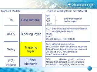
Slab-Symmetric Dielectric-Based Accelerator. Rodney Yoder UCLA PBPL / Manhattan College. DoE Program Review UCLA, May 2004. Review: Why Slab Geometry?. Interested in structures in the mm or FIR regime But— there are well-known limitations:. Cavity structures:

E N D
Slab-Symmetric Dielectric-Based Accelerator Rodney Yoder UCLA PBPL / Manhattan College DoE Program Review UCLA, May 2004
Review: Why Slab Geometry? • Interested in structures in the mm or FIR regime • But— there are well-known limitations: Cavity structures: • Wakefields ~ l3, leadingto bad transverse dynamics • Machining tolerances are tough • Accelerating fields limited by breakdown Slab structure: • Transverse wakefields strongly suppressed • Planar structure may be easier to build and tune • Dielectric breakdown limit potentially easier R. Yoder / DoE Review
Slab-Symmetric Dielectric-Loaded Accelerator R. Yoder / DoE Review
Motivation: experiment • UCLA project begun mid 1990s, hampered by small device dimensions at 10 µm • Scaling to 340 µm gives realistic device dimensions for injection • Neptune photoinjector beam a good candidate (E = 11–14 MeV, en = 6π mm mrad, DE/E = 0.1%, 4 ps bunch length, chicane compressor, can focus to ~ 20-30 µm “slab” beam) • Potential for high-power THz generation, using Neptune CO2 laser / MARS amplifier (≤ 100 J/pulse) • “Cold-testing” with 10-µm design still possible R. Yoder / DoE Review
Basic physics of the structures • • Set l = l0 (vacuum wavelength of laser) • • Fields independent of x (translational symmetry) • • Dispersion relation: = c2(kx2 + ky2 + kz2) • Periodic coupling enforces kz = w/c vfz = c • • prevents Fabry-Perot mode • Since kx = 0, we must have ky = 0 in gap • Resonantkz values obtained as function of geometry using dielectric to match boundary conditions R. Yoder / DoE Review
Ideal accelerating mode, 3D simulation Structure Q ~ 600, r/Q = 25 k/m, so field = 30 MV/m at 50 MW R. Yoder / DoE Review
Transverse Wakefield Suppression 2D Simulations using OOPIC Long pulse (s = 4 ps) Short pulse (s = 0.4 ps) Wz W 200 pC, sr = 120 µm, er = 3.9, a = 0.58 mm, b = 1.44 mm R. Yoder / DoE Review
Coupling to the structures • Periodic slots enforce resonant mode • slot dimensions determine the Q-factor for the structure • roughly proportional to l0/w, but filling time depends on depth too • Very wide slots are NOT cut off! • slots fill with field • resonant frequency is perturbed • high fields on slot surfaces • For small slots, Dw/w ~ L/w • Perturbation vanishes for L = lg/4 (quarter-wave matching) • gives high Q, slow fill R. Yoder / DoE Review
2D time-dependent simulation 340 µm wavelength a = 115 µm, b–a = 30 µm quarter-wavelength slots Axial field: • flat wavefronts (no perturbation) • large field in slot Transverse field: • zero at y=0 • zero at peak acceleration R. Yoder / DoE Review
Comparison: Shorter coupling slots a = 118 µm, b–a = 16.9 µm silicon (n = 3.41) slots 6 µm long, 5 µm wide Resonant at 334 µm (Dw /w = +1.8%) Slight deformation near slot Field in slot comparable to peak Frequency bandwidth ~ 1% R. Yoder / DoE Review
Filling Everything depends on the slots… Quarter-wavelength slots t = 325 ps Emax = 15 E0 6 µm slots t = 70 ps Emax = 3.8 E0 R. Yoder / DoE Review
Manufacture • Can use standard semiconductor techniques • Choices are monolithic vs. two-part • Monolithic • alignment not an issue • how to tune/deform? • must avoid very thin “membrane” as upper layer • Two-part • easy tuning • how to align? • need precision positioning in y, z, and azimuthal angle • possible but expensive R. Yoder / DoE Review
Multilayer structure for 1-10µm laser(aka 1-D Photonic Band Gap Accelerator!) • Metal boundaries won’t work well at IR • Investigate dielectric multilayer approach (Bragg reflector) • Simulations underway R = 99.2% 9 layers plus substrate Each layer is a quarter wavelength R. Yoder / DoE Review
Conclusions • Slab structures are attractive for beam quality and gradient; become practical at (sub-)THz for e.g. Neptune • We are completing designs for versions with and without metal (scalability to IR) • Simulations look good for acceleration; structure cold-tests will be necessary to build and align • Working out fabrication issues • Questions: Breakdown limits, wakefields • Acceleration gradients potentially worth the effort R. Yoder / DoE Review