Download
1 / 36
360 likes | 492 Vues
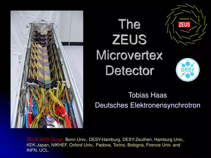
The ZEUS Microvertex Detector. Tobias Haas Deutsches Elektronensynchrotron. ZEUS MVD Group: Bonn Univ., DESY-Hamburg, DESY-Zeuthen, Hamburg Univ., KEK-Japan, NIKHEF, Oxford Univ., Padova, Torino, Bologna, Firenze Univ. and INFN, UCL. Today:. Motivation Hardware DAQ & R/O DQM

E N D
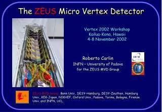
The ZEUS Microvertex Detector Tobias Haas Deutsches Elektronensynchrotron ZEUS MVD Group:Bonn Univ., DESY-Hamburg, DESY-Zeuthen, Hamburg Univ., KEK-Japan, NIKHEF, Oxford Univ., Padova, Torino, Bologna, Firenze Univ. and INFN, UCL.
Today: • Motivation • Hardware • DAQ & R/O • DQM • Radiation monitoring • Alignment/Tracking • Summary MVD Tutorial, Tobias Haas, DESY
Requirements, Constraints, History • Constraints: • Fit into existing ZEUS detector, • < Central tracker inner diameter (~32 cm) • > elliptical beampipe (max. ~12 cm) • Bunch crossing time 96 ns • Operation at room temperature • Extended interaction region in z direction • Requirements: • < 100 μm impact parameter resolution: • < 20 μm intrinsic point resolution, • 3 spatial measurements in two projections for each track, • High (>97%) track efficiency. • History: • 1997: Approval • 1997 – 2000: Construction • 2000: First Cosmics • 2001: Installation is ZEUS MVD Tutorial, Tobias Haas, DESY
Physics Charm Beauty MVD Tutorial, Tobias Haas, DESY
MVD in Numbers • 3(2) Barrel layers, 4 forward planes • 38 mm < R < 247 mm • -300 mm < Z < 750 mm • 7.60 < θ < 1600 • Radiation < 300 kRad • 207360 channels • >99% single hit efficiency • Currently: • ca 12k dead channels (5.7%) • 50 – 60 μm single hit resolution (goal: 20 – 30 μm) • 130 – 150 μm vertex resolution (goal: < 100 μm) MVD Tutorial, Tobias Haas, DESY
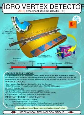
All cables in a Faraday cage • The barrel section: • 30 ladders • each one composed of 5 modules of 4 Si detectors • Total of 300 hybrids, >150k channels • The forward section: • 4 wheels • each one composed by 2 layers of 14 Si detectors • Total of 112 hybrids, >50k channels • The read section: • Cooling pipes and manifolds • Distribution of FE, slow control and alignment cables Overview of the ZEUS MVD MVD Tutorial, Tobias Haas, DESY
125 mm 64 mm • Five modules are mounted on a carbon fiber support structure to form a ladder. • The Si planes, Hybrids and Cabling are located on the 3 planes of the ladder • 30 ladders, in 3 planes, are positioned around the elliptical beam pipe in the MVD barrel detector Barrel • Single sided n-doped silicon sensors, 300 μm thick, p+ strip implants, • Every 6th read out (120 μm R/O pitch), • RΦ and Z sensors are ganged, • Two planes are glued together to form a module with x-y readout. • Helix3.0 analog R/O chip (Heidelberg/NIKHEF) MVD Tutorial, Tobias Haas, DESY
The forward wheels have differently shaped detectors (trapezoidal with two different sizes to accommodate the beam pipe), • Two layers of single sided detectors, same pitch and construction as in the barrel, • strips cross at an angle of 26°. Forward Wheels • Same electronics and connectivity as in the barrel MVD Tutorial, Tobias Haas, DESY
Sensor/RO/Module Sensor (Design) Helix (RO) Half Module MVD Tutorial, Tobias Haas, DESY
per barrel layer MVD Tutorial, Tobias Haas, DESY
Patch Box To platform to detector MVD Tutorial, Tobias Haas, DESY
Other Components Racks close to Veto wall area Cooling/SC HV/LV ADCs MVD Tutorial, Tobias Haas, DESY
Signals digitized signal S/N ~12-15 analog signal MVD Tutorial, Tobias Haas, DESY
dE/dx MVD Tutorial, Tobias Haas, DESY
Detector Status (Pedestal run) Barrel MVD • Disabled Chips • C1L05M0 Hlx 4-7 • C1L07M0 All • C1L07M4 Hlx 4-7 • C2L00M3 Hlx 5 • C2L01M0 Hlx 4-7 • C2L02M4 All • C2L05M0 Hlx 4-7 • C2L09M4 Hlx 4-7 • C2L15M4 Hlx 4-7 • Masked in DAQ • since last Mar. • C1L00M2 All • C1L02M2 All • C2L09M2 Hlx 4 • W3S11 All Forward MVD MVD Tutorial, Tobias Haas, DESY
Detector Monitoring and Status: • Dedicated runs (taken daily or when machine schedule allows): • Pedestals (noise) • Test pulse runs (gain and timing) • IV curves (bulk damage) • Laser alignment (mechanical stability) • Online DQM: • Parasitic monitoring: • occupancies, • cluster charges and widths • Immediate feedback for shiftcrew (hip) • Offline DQM: • Dedicated analysis of archived data before reconstruction: • Occupancies, • Cluster charges and widths • Hit maps • Bad/Noisy channel maps for reconstruction (→ gaf) DQM DB All Results MVD Tutorial, Tobias Haas, DESY
4x2 PIN diodes 4x2 PIN diodes 8 RadFET FMVD BMVD 4 RadFET 8 RadFET 4 RadFET -100 cm -130 cm 110 cm -60 cm -120 cm z=160 cm Radiation Monitoring zx-Querschnitt Z X • PIN diodes: Instantaneous dose from signal current (photo effect) → beam dump • RadFETs:Integrated dose (Rad damage in FET → shift in threshold voltage)
RADFET Doses -1.1m -0.6m -1.3m -1.7m MVD Tutorial, Tobias Haas, DESY
Radiation Effects • Signal: ↓ • Noise: ↑ • Sensor leakage currents: ↑ Signal (ADC Counts) August 2002 Nosie (ADC Counts) Leakage (μA) MVD Tutorial, Tobias Haas, DESY August 2002
Bad Modules forward rear bad Sensor Leakage Currents (measures radation dose) forward MVD Tutorial, Tobias Haas, DESY
Bad Channels MVD Tutorial, Tobias Haas, DESY
? MVD Tutorial, Tobias Haas, DESY
MVD Reconstruction Suite • MVRECON (table: MVRECC) • Standalone MVD reconstruction • Calibrations, Dead Channel Treatment • Clustering • VCRECON, Pass 1 (table: ZTPRHL) • Pattern Recognition • First Track Fit • KFRECON (table ZTTRHL, ZTTRPRM) • Kalman Filter + Track Fit • VCRECON, Pass 2 • Primary and Secondary Vertexing Iteration is possible… … but not really foreseen … MVD Tutorial, Tobias Haas, DESY
MVRECON Cluster ADC Counts Cluster Threshold Strip Threshold Strips • Clustering a la “Online” • Cluster + Strip Threshold • Allow one strip below threshold • Add on the two side strips below threshold • Position Reconstruction MVD Tutorial, Tobias Haas, DESY
All CTD tracks > 4 MVD hits > 2 MVD hits Efficiencies Simulation # Tracks Φ Data Note: Acceptance holes Φ • Efficiency estimates from NC DIS: (Tracks in CTD and MVD fiducial) • > 4 MVD hits > 2 MVD hits • Data 91.4% 99.3% • MC 93.8% 99.3% MVD Tutorial, Tobias Haas, DESY
Propaganda Events Q2 1200 GeV2 Charged Current Q2 4500 GeV2 Charged Current Q2 2800 GeV2 Neutral Current MVD Tutorial, Tobias Haas, DESY
Alignment • 3 Step process: • Survey of ladder positions before installation in the lab, • Final alignment using cosmic data, • Monitoring of stability using an in situ laser system with semi-transparent position sensors. MVD Tutorial, Tobias Haas, DESY
σ=335μm σ=1604μm Global alignment σ=289μm σ=1502μm σ=97μm σ=116μm Internal alignment σ=64μm σ=47μm Current Alignment Track Residuals Impact Parameter MVD Tutorial, Tobias Haas, DESY
Only 1 (!) alignment exists Barrel could be better… … but the wheels have not even been touched. Still dependent on standalone cosmic runs cosmics taken during beam are being studied … Alignment … comments Barrel Wheels MVD Tutorial, Tobias Haas, DESY
Questions to the alignment • alignment procedure • position reconstruction in mvrecon • Effects of magnetic field • long term stability MVD Tutorial, Tobias Haas, DESY
Peformance Estimate (R. Mankel) • D* tagged events allow to investigate the distance-of-closest approach (DCA) of the helices of K– and + • DCA resolution-per-track (DCA/√2) is a measure related to the impact parameter resolution • independent of vertexing • averaged over longitudinal (Z) and transverse (DH) resolutions • Compare to H1 published impact parameter resolution • IP=33m (90 m /pT) • At MC level our resolutions look reasonable • Data: alignment key issue ZEUS data (2004 e+) ZTT H1 IP resolution(1/pT 1.4/p) MC ZEUS MC ZTT
Alignment Monitoring: Laser Alignment Typical Example of Measurement • 5 laser beams (780nm, 5 mW), 7 sensors/beam, • Sensor gives position to 10μm, • Data taken once per fill, • Monitor deformations and define period of stability. MVD Tutorial, Tobias Haas, DESY
Stability < 20 μm MVD Tutorial, Tobias Haas, DESY
! MVD Tutorial, Tobias Haas, DESY
Summary • ZEUS MVD has completed the commissioning phase, i. e. design goals have been reached: • Reliable and well monitored detector operation (Data quality, radiation, alignment), • High tracking efficiency (>99%), • Precision needs to reach the goal (Impact parameter resolution < 100 μm ). • Dead channel development is worrying • Irradiation is under control but a constant concern. • Alignment work needs to progress MVD Tutorial, Tobias Haas, DESY