Download
1 / 14
160 likes | 364 Vues
WEARABLE NAVIGATION DEVICE FOR THE BLIND. MAY 18, 2012. MSD II - TEAM P12016. PRESENTATION AGENDA. Agenda (Outline for now) Team Roles Intro to Project Summary of Requirements System Architecture Physical Prototype Major Components Snap Stresses & Plastic Tolerances Testing

E N D
WEARABLE NAVIGATION DEVICE FOR THE BLIND MAY 18, 2012 MSD II -TEAM P12016
PRESENTATION AGENDA • Agenda (Outline for now) • Team Roles • Intro to Project • Summary of Requirements • System Architecture • Physical Prototype • Major Components • Snap Stresses & Plastic Tolerances • Testing • Test Results & Data • Final Spec Comparison • Lessons Learned • Future Work • Q & A
TEAM ROLES • Oliver Wing | CE • Path-finding algorithm • Path-following algorithm • Software & functionality testing • Magy Yasin | ISE • Scheduling • Test creation & documentation • Attachment manufacture • Curtis Beard | EE • PCB design • Testing & support • Dave Taubman | EE • PCB design • PCB testing & support • Algorithm creation • Stu Burgess | ME • Plastic enclosure design • Mechanical assembly & tolerances • Thermal modeling • Jeff Chiappone | ME • Plastic enclosure design • Stress testing • Poster design • Aalyia Shaukat | EE • PCB design • Testing & support ?
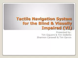
PROJECT INTRODUCTION • Description: • The blind face numerous challenges when navigating inside buildings • Braille not always helpful - only about 10% of the blind read Braille • Team focused on creating a small electronic device for this purpose • Prior teams’ accomplishments: • Working prototype was created • Very heavy, bulky, enclosure did not contain all components • Goals for this project: • Dramatically reduce size and weight • Make device less conspicuous • Make device portable and allow enclosure to contain all components
REQUIREMENTS SUMMARY • Blind individuals needed a device that: • Was lightweight, fairly conspicuous, easy to use and learn • Guided them towards a destination, warned when they detracted • Provided non-visual/non-auditory feedback (not Braille) • In general, device needed to be: • Resilient, able to withstand a 3-foot drop • Able to allow the user change the battery in less than a minute
SYSTEM ARCHITECTURE Dave, Olliver, (Jackson?)
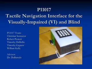
PHYSICAL PROTOTYPE
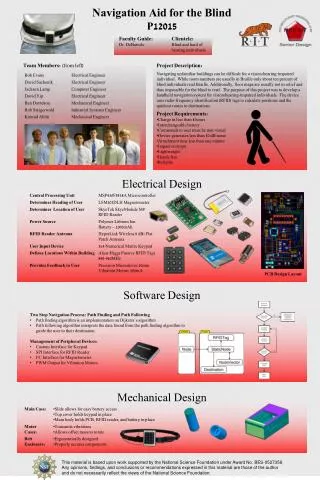
Printed circuit board • Links together all other electronics • Contains micro-controller unit • Vibrational motors • Send out long or pulsed vibrational feedback • User senses these and interprets for directions • RFID tag reader • Acts as the “eyes” of the device • Senses RFID tags in building • Numeric keypad • Takes room number input from user • Magnetometer • Keeps device working properly in any orientation • Antenna • Senses RFID tags for reader • Plastic enclosure • Houses all electronics • Allows easy access to battery • Elastic sleeve • Holds electronics to body • Keeps device secure and wearable MAJOR COMPONENTS
Fig 1: Successful and unsuccessful snap orientation Fig 2: Original prototype housing with very loose fit SNAP STRESS & PLASTIC TOLERANCE • Snaps: • Largely dependent on manufacture orientation (Fig 1): • Length and width carefully chosen to withstand plastic stress limits • Plastic tolerances: • Rapid-prototype machine subject to +/- extra layer of .007’’ plastic • Largest factor in number of prototypes made (Fig 2); fit needed to be perfect
90% 92% 98% 98% 100% 100% Image of thermal test results? Image of Ansys model? TESTING • Drop Tests: • Qualification: device needed to survive fall of 3 feet onto concrete surface • Result: device passed, no fracture of cracking of plastic housing or other components during fall • Ergonomic Testing: • Qualification: highest percentage of vibrations perceived over all other locations • Result: three distinct locations chosen with specific distance determined by additional qualitative testing. • Thermal Testing: • Qualification: air inside device can not exceed ___ degrees F • Result: housing successfully dissipates enough heat during use to meet the qualification
TEST RESULTS & DATA Do we still need this if we can fit all the test stuff on one slide? How much detail do we need for testing?
COMPARISON TO SPECIFICATIONS Magy, Stu, Dave
LESSONS LEARNED • Mechanical: • The time for ideation is slim--brainstorm quickly, then arrive at a solution • Consider local vendors for quick (<1 day) turn around and last-second items • Rapid prototyping is a successful choice for quick turn-around and cost effectiveness • Rapid prototyping will always be much less precise than expected-plan accordingly for fit and tolerances • Electronic: • Learn necessary software algorithms for path-finding and path-following during MSD I • Collaborate directly with other teams or previous team/project members if possible • Always plan for 1-2 weeks of changes/debugging to PCB even if design seems finalized • Scheduling: • Anything to add here?
FUTURE WORK All