Download
1 / 1
10 likes | 88 Vues
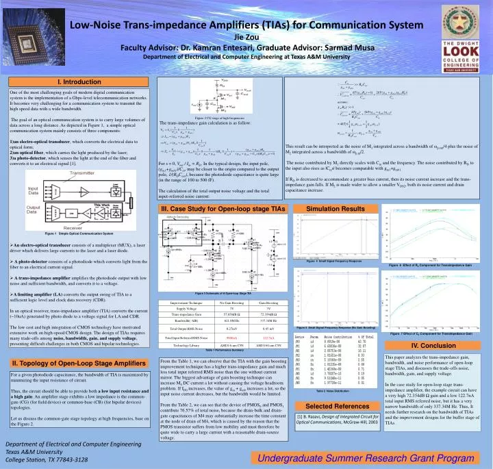
I. Introduction. Figure 2 CG stage at high frequencies The trans-impedance gain calculation is as follow:

E N D
I. Introduction Figure 2 CG stage at high frequencies The trans-impedance gain calculation is as follow: For s = 0, Vout / Iin = RD. In the typical design, the input pole, (gm1+gmb1)/Cin, may be closer to the origin compared to the output pole, 1/(RDCout), because the photodiode capacitance is quite large (in the range of 100 to 500 fF). The calculation of the total output noise voltage and the total input-referred noise current: This result can be interpreted as the noise of M1 integrated across a bandwidth of ωp,out/4 plus the noise of M2 integrated across a bandwidth of ωp,in/2. The noise contributed by M1 directly scales with Cin and the frequency. The noise contributed by RD to the input also rises as |Cins| becomes comparable with gm1+gmb1. If RD is decreased to accommodate a greater bias current, then its noise current increase and the trans-impedance gain falls. If M2 is made wider to allow a smaller VDS2, both its noise current and drain capacitance increase. • One of the most challenging goals of modern digital communication system is the implementation of a Gbps-level telecommunication networks. It becomes very challenging for a communication system to transmit the high speed data with a wide bandwidth. • The goal of an optical communication system is to carry large volumes of data across a long distance. As depicted in Figure 1, a simple optical communication system mainly consists of three components: • an electro-optical transducer, which converts the electrical data to optical form; • an optical fiber, which carries the light produced by the laser; • a photo-detector, which senses the light at the end of the fiber and converts it to an electrical signal [1]. • Figure 1 Simple Optical Communication System • An electro-optical transducer consists of a multiplexer (MUX), a laser driver which delivers large currents to the laser and a laser diode. • A photo-detector consists of a photodiode which converts light from the fiber to an electrical current signal. • A trans-impedance amplifier amplifies the photodiode output with low noise and sufficient bandwidth, and converts it to a voltage. • A limiting amplifier (LA) converts the output swing of TIA to a sufficient logic level and clock data recovery (CDR). • In an optical receiver, trans-impedance amplifier (TIA) converts the current (~10uA) generated by photo diode to a voltage signal for LA and CDR. • The low cost and high integration of CMOS technology have motivated extensive work on high-speed CMOS design. The design of TIAs requires many trade-offs among noise, bandwidth, gain, and supply voltage, presenting difficult challenges in both CMOS and bipolar technologies. Low-Noise Trans-impedance Amplifiers (TIAs) for Communication SystemJie Zou Faculty Advisor: Dr. Kamran Entesari, Graduate Advisor: Sarmad Musa Department of Electrical and Computer Engineering at Texas A&M University III.Case Study for Open-loop stage TIAs Simulation Results Figure 4 Small Signal Frequency Response Figure 6 Effect of R0 Component for Transimpedance Gain Department of Electrical and Computer Engineering Texas A&M University College Station, TX 77843-3128 Figure 3 Schematic of A Open-loop Stage TIA Figure 5 Small Signal Frequency Response (No Gain Boosting) Figure 7 Effect of C0 Component for Transimpedance Gain IV.Conclusion Table 1 Performance Summary This paper analyzes the trans-impedance gain, bandwidth, and noise performance of open-loop stage TIAs, and discusses the trade-offs noise, bandwidth, gain, and supply voltage. In the case study for open-loop stage trans-impedance amplifier, the example circuit can have a very high 72.354dB Ω gain and a low 122.7nA total input RMS referred noise, but it has a very narrow bandwidth of only 337.34M Hz. Thus, It needs further research on the bandwidth of TIAs and the improvement designs for the buffer stage of TIAs. From the Table 1, we can observe that the TIA with the gain boosting improvement technique has a higher trans-impedance gain and much less total input referred RMS noise than the one without current mirror. The biggest advantage of gain boosting technique can increase M0 DC current a lot without causing the voltage headroom problem. If ID0 increases, the value of gm + gmb increases a lot, so the input noise current decreases, but the bandwidth would be limited. From the Table 2, we can see that the device of PMOS0 and PMOS1 contribute 76.57% of total noise, because the drain-bulk and drain-gate capacitances of M4 may substantially increase the time constant at the node of drain of M4, which is caused by the reason that the PMOS transistor suffers from low mobility and must therefore be quite wide to carry a large current with a reasonable drain-source voltage. II. Topology of Open-Loop Stage Amplifiers For a given photodiode capacitance, the bandwidth of TIA is maximized by minimizing the input resistance of circuit. Thus, the circuit should be able to provide both a low input resistance and a high gain. An amplifier stage exhibits a low impedance is the common-gate (CG) (for field device) or common-base (CB) (for bipolar devices) topologies. Let us discuss the common-gate stage topology at high frequencies, base on the Figure 2. Table 2 Noise Distribution Selected References [1] B. Razavi, Design of Integrated Circuit for Optical Communications, McGraw-Hill, 2003 Undergraduate Summer Research Grant Program