Download
1 / 43
510 likes | 857 Vues
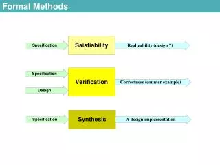
Formal Methods. Why formal methods?. Informal methods are open to interpretation and ambiguity, and often incomplete and inconsistent. Formal methods have some basis in mathematics and allow us to reason about the system we are building.

E N D
Why formal methods? • Informal methods are open to interpretation and ambiguity, and often incomplete and inconsistent. • Formal methods have some basis in mathematics and allow us to reason about the system we are building. • They help us accurately capture our intent so that it is precise and clear to others. • There are lots of different formal methods. • Like programming languages, each formal methods has strengths and weaknesses. • Like programming languages, some formal methods are tailored to a specific problem domain, e.g., real-time systems requiring a discussion of temporal semantics. • Formal methods are used to specify aspects of the software system – behavior, data relationship, temporal semantics
Why aren’t they used everywhere? • Formal methods are controversial. Their advocates claim that they can revolutionize [software] development. Their detractors think that they are impossibly difficult. Meanwhile, for most people, formal methods are so unfamiliar that it is difficult to judge the competing claims. – Anthony Hall, 1990. • We will gain an appreciation of formal methods over the next few lectures to understand their impact on software engineering in the years to come.
Formal methods - limitations • Formal methods have not become mainstream software development techniques as once predicted. • Other SE techniques have been successful at increasing software quality, so the need to formalism has decreased. • Economic pressures make time-to-market a key driver, rather than a low error count. Formal methods do not reduce time to market. • Formal methods are had to scale to large software systems. • Scope of formal methods is limited – not well suited to specifying and analyzing user interfaces and user interactions. • Formal methods have limited practical applicability. • Principle benefit is reduction in number of errors. Main area of applicability is critical systems.
Deficiencies of informal methods • Natural language (English) is an example of an informal method. • It is often ambiguous, incomplete, insufficient, and contains contradictions and mixed levels of abstractions. • We often try to address these deficiencies by supplementing the natural language description with diagrams. • These diagrams often lack structure and have similar deficiencies to natural language. • Coupled with sloppiness in analysis and design, poor attention to detail and the lack of thorough reviews, the use of informal methods can lead to a software disaster.
Problems • Contradiction – sets of statements that are in variance with each other. They are often written by different people and separated by many pages in the specification. They are therefore difficult to detect. • Ambiguity – statements that can be interpreted in a number of ways. They usually do not appear ambiguous to the author. • The operator identity consists of the operator name and password; the password consists of six digits. It should be displayed on the security VDU and deposited into the login file when an operator logs into the system. • What does “it” refer to – the operator or the password?
Problems • Vagueness – often occurs because the spoecification document is bulky. Achieving a high level of precision consistently is an almost impossible task. • The interface to the system used by the radar operators should be user-friendly. • The above statement contains no useful information! • Incompleteness – missing details such as a failure to specify what should occur in certain conditions. • The system should maintain the hourly level of the reservoir from depth sensors in the reservoir. These values should be stored for the past six months. • The function of the AVERAGE command is to display on a PC the average water depth for a particular sensor between two times. • What happens if the user specifies a period greater than six months?
Problems • Mixed levels of abstraction – leads to difficulty in seeing the overall functional architecture of a system. • For example, if the following statements were intermixed: • The purpose of the system is to track the stock in a warehouse. • When the loading clerk types in the withdraw command he or she will communicate the order number, the identity of the item to be removed, and the quantity removed. The system will respond with a confirmation that the removal is allowable. • This leads to a lack of clarity.
Elevator problem • Let us define the elevator problem as: • We need to move n elevators between m floors. • Each elevator has a set of m buttons, one for each floor. These illuminate when pressed and cause the elevator to visit the corresponding floor. The illumination is cancelled when the corresponding floor is visited by the elevator • Each floor, except the first floor and the top floor has two buttons, one to request an up-elevator, and one to request a down-elevator. These buttons illuminate when pressed. The illumination is cancelled when an elevator visits the floor and then moves in the desired direction. • When an elevator has no requests, it remains at tis current floor with its doors closed.
Finite state machines • In each of the n elevators, there are m buttons – one for each floor. These are called elevator buttons (EB). • One each floor there are two buttons to request an up and down elevator. These are called floor buttons (FB). • Let EB(e, f) denote the button in elevator e that is pressed to request floor f. • EB(e, f) can be in two states: • EBON(e, f): Elevator Button (e, f) ON. • EBOFF(e, f): Elevator Button (e, f) OFF. • If the button is on and the elevator arrives at floor f, then the button is turned off. If the button is off, and it is pressed, then the button comes on. • These two events are: • EBP(e, f): Elevator Button (e, f) Pressed. • EAF(e, f): Elevator e Arrives at Floor f.
Finite state machines • The state transition diagram for an elevator button is given above. • We introduce a predicate: • V(e, f): Elevator e is Visiting floor f. • A predicate is a boolean function. • If elevator button (e, f) is off (current state) and elevator button (e, f) is pressed (event) and elevator e is not visiting floor f (predicate), then the button is turned on. EBOFF(e, f) ∧ EBP(e, f) ∧ ⌐V(e, f) ⇒ EBON(e, f) EBP(e, f) EBOFF(e, f) EBON(e, f) EAF(e, f)
Finite state machines • If the elevator is visiting floor f when button (e, f) is pressed, then nothing happens. • If the elevator arrives at floor f and the button is on, then it is turned off. EBON(e, f) ∧ EAF(e, f) ⇒ EBOFF(e, f) • Now we consider the floor buttons. • FB(d, f) denotes the button on floor f that requests an elevator traveling in direction d. • Each button has two states: • FBON(d, f): Floor Button (d, f) is ON. • FBOFF(d, f): Floor Button (d, f) is OFF.
Finite state machines • If the button is on and an elevator arrives at floor f traveling in direction d, then the button is turned off. • If the button is off, and it is pressed, then the button comes on. • These events are: • FBP(d, f): Floor Button (d, f) Pressed • EAF(1..n, f): Elevator 1 or … or Elevator n Arrives at floor f. • Note a..b to denote disjunction. We use P(a, 1..n, b) to denote: P(a, 1, b) ∨ P(a, 2, b) ∨ … ∨ P(a, n, b) FBP(d, f) FBOFF(d, f) FBON(d, f) EAF(1..n, f)
Finite state machines • We define predicate S as follows: S(d, e, f): Elevator e is visiting floor f and the direction in which it is about to move is either up (d = U), down (d = D), or no requests are pending (d = N) • This predicate is actually a state. • The transition rules for floor buttons is then: FBOFF(d, f) ∧ FBP(d, f) ∧ ⌐S(d, 1..n, f) ⇒ FBON(d, f) FBON(d, f) ∧ EAF(1..n, f) ∧ S(d, 1..n, f) ⇒ FBOFF(d, f), d=D∨U • V(e, f) can be defined in terms of S(d, e, f) V(e, f) = S(U, e, f) ∨ S(D, e, f) ∨ S(N, e, f)
Finite state machines • Three elevator states can be defined: • M(d, e, f): Elevator e is Moving in direction d (floor f is next) • S(d, e, f): Elevator e is Stopped (d-bound) at floor f • W(e, f): Elevator e is Waiting at floor f (door closed) • Other interesting events include: • DC(e, f): Door Closed for elevator e at floor f • ST(e, f): Sensor Triggered as elevator e nears floor f • RL: Request Logged (button pressed) • Rules governing movement are: S(U, e, f) ∧ DC(e, f) ⇒ M(U, e, f+1) S(D, e, f) ∧ DC(e, f) ⇒ M(D, e, f-1) S(N, e, f) ∧ DC(e, f) ⇒ W(e, f)
Finite state machines M(U, e, f+1) M(D, e, f) ST(e, f) DC(e, f) RL RL S(U, e, f) S(N, e, f) S(D, e, f) DC(e, f) DC(e, f) RL W(e, f) RL RL ST(e, f) M(U, e, f) M(D, e, f-1)
Finite state machines • The finite state machine is more precise than a natural language or graphical representation. • It is almost as easy to understand • It doesn’t scale well to problems with many states. • Finite state machines do not handles the concept of time. For this one has to use an extension of finite state machines called a statechart,
Petri nets • A major problem with specifying concurrent systems is dealing with timing. • The problem manifests itself in many ways: • Synchronization • Race conditions • Deadlock • Timing problems can be a result of poor design or implementation, which are in turn a result of poor specification. • Petri nets are a powerful technique for sepcifying and designing systems with potential timing problems. • Petri nets were invented by Carl Adam Petri in 1962.
Petri nets - introduction • A Petri net consists of 4 parts: a set of places P; a set of transitions T; an input function I; and output function O. • The set of places P = {p1, p2, p3, p4} • The set of transitions T = {t1, t2} • The input functions for the transitions are: • I(t1) = {p2, p4} • I(t2) = {p2} • The output functions for the transitions are: • O(t1) = {p1} • O(t2) = {p3, p3} p2 t2 t1 p3 p1 p4
Petri nets - introduction • More formally, a Petri net is a 4-tuple, C = (P, T, I, O) • P = {p1, p2, …, pn} is a finite set of places, n ≥ 0, • T = {t1, t2, …, tm} is a finite set of transitions, m ≥ 0 P & T are disjoint. • I: T → P is the input function, a mapping from transitions onto bags of places. • O: T → P is the output function, a mapping from transitions onto bags of places. • The marking of a Petri net is the assignment of tokens to that Petri net.
Petri nets - introduction p2 • The Petri net above contains 4 tokens. • The marking can be represented by the vector (1, 2, 0, 1). • Transition t1 is enables (ready to fire) because there are tokens in p2 and p4. • If the transition fires, 1 token is removed from p2 and p4, and 1 token is added to p1. • Note that the number of tokens if not conserved. t2 t1 p3 p1 p4
Petri nets - introduction • Petri nets are nondeterministic. If more than 1 transition could fire, one is selected arbitrarily. • In the previous slide, both t1 and t2 are enabled. If t1 fires, the resultant marking becomes (2, 1, 0, 0). • Formally a marking M of a Petri net C = (P, T, I, O), is a function from the set of places P to te set of non-negative integers: • M: P → (0, 1, 2, …) • A marked Petri net is then a 5-tuple (P, T, I, O, M).
Petri net - introduction • An extension to a Petri net is an inhibitor arc. • A transition is enabled if there is a token on each of its (normal) input arcs, and no token on any inhibitor input arcs. • Transition t1 is enabled below. p2 t2 t1 p3 p1 p4
Petri nets – elevator problem • There are n elevators installed in a building with m floors. • Each floor is represented by a place, Ff, 1 ≤ f ≤ m. • An elevator is represented by a token. • A token in Ff denotes that an elevator is at floor f. • Constraint • Each elevator has a set of m buttons – one for each floor. • These are illuminated when pressed, cause the elevator to travel to that floor, and turned off when the elevator arrives at that floor. • Additional places are needed to model this. • The elevator button for floor f in elevator e is denoted EBf, e with 1 ≤ f ≤ m, 1 ≤ e ≤ n • For the sake of simplicity we suppress the subscript e denoting the elevator.
Petri nets – elevator problem • A token in EBf denotes that the elevator button for floor f is illuminated. • Assume that EBf is not initially illuminated. • Note that the button is illuminated the first time it is pressed and subsequent presses do nothing (until elevator arrives that the correct floor). • Assume that the elevator is currently at floor g. EBf is pressed Elevator in action Ff EBf Fg
Petri nets – elevator problem • Each floor has two buttons (except the bottom and top floors) to represent an up-elevator and a down-elevator. These buttons illuminate when pressed, and are cancelled when an elevator traveling in the right direction arrives at the floor. • The floor buttons are represented by places FBdf and Fbuf • The situation when an elevator reaches floor f from floor g with one or both buttons illuminated is given by:
Petri nets – elevator problem FBuf is pressed Elevator in action Ff FBuf Fg FBdf is pressed Ff FBdf Elevator in action
Petri nets – elevator problem • When an elevator has no requests in needs to remain on the same floor. • This is easily achieved, • If there are no requests, no “Elevator in action” is enabled.
Petri nets - properties • Petri nets have some additional useful properties. • It is possible to prove that the system has no deadlocks or livelocks. • They can be used to perform a proof of correctness. • The system is simple and can be implemented as part of a tool.
Z • Z is a popular formal specification language. • See Schach page347 for a discussion on the pronunciation of Z (zed). • Use of Z requires knowledge of set theory, functions and discrete mathematics, including first-order logic. • Like the earlier formal systems examined, there are several variants of Z.
Z • In its simplest form a Z specification consists of 4 sections: • Given sets, data types, and constants • State definitions • Initial state • Operations • It uses standard set and logic operators: ∃, ⊃, ⇒ • It uses some additional symbols such as ⊕, ↦, ⊲.
Z • Given sets • A Z specification begins with a list of given sets. These are sets that need not be defined in detail. • The names of given sets appears in brackets, e.g., [Button] to represent the set of buttons in the elevator problem. S declarations predicates
Z • State definition • A Z specification consists of a number of schemata. • Each schemata consists of a group of variable declarations and a list of predicates that constrain the values of the variables. • A schemata S is defined as: S declarations predicates
Z • For the elevator problem, there are four subsets of Button: • floor buttons • elevator buttons • buttons (the set of all buttons in the elevator problem) • pushed (the set of buttons that have been pushed and are therefore on). • The symbol ℙ denotes powerset (the set of all subsets of a given set).
Z Button_State floor_button elevator_button: ℙ Button buttons: ℙ Button pushed: ℙ Button floor_button ⋂ elevator_button = ∅ floor_button ⋃ elevator_button = buttons
Z • Initial state • The abstract initial state describes the state of the system when it is first turned on. • For the elevator problem the initial state is: Button_init ≘ [Button_State′ | pushed′ = ∅] • This is a vertical schema definition (as opposed to a horizontal one). • The initial state above tells us that when the elevator is first turned on, the set pushed is initially empty; that is, all buttons are off.
Z • Operations • If a button is pushed for the first time, then that button is turned on and added to the set pushed. • The ∆ in the first line of the schema tells us that operation changes the state of Button_State. • The operation has one input variable, button?. The ? symbol denotes an input variable, whereas the ! symbol denotes an output variable. Push_Button ∆Button_State button?: Button (button? ∈ buttons) ∧ (((button? ∉ pushed) ∧ (pushed′ = pushed ∪ {button?})) ∨ ((button? ∈ pushed) ∧ (pushed′ = pushed)))
Z • The predicate part of the operation consists of a group of preconditions that must hold before the operation is invoked, and a group of postconditions that must hold after the operation is complete. • If the operation is invoked without the preconditions being satisfied, then unspecified (read unpredictable) results occur. • pushed′ denotes an updated value of pushed.
Z • When an elevator arrives at a floor, if the corresponding floor button is on, then it must be turned off, similarly for the corresponding elevator button. • The symbol \ denotes set difference • The solution below is an oversimplification on that it does not distinguish between up and down floor buttons. Floor_Arrival ∆Button_State button?: Button (button? ∈ buttons) ∧ (((button? ∈ pushed) ∧ (pushed′ = pushed \ {button?})) ∨ ((button? ∉ pushed) ∧ (pushed′ = pushed)))
Z • Z is fairly widely used and has been employed on some large scale projects. • Easy to find faults in Z specifications, especially during inspections of the specification, and inspection of the design and/or code against the formal specification. • Need to be precise when using Z, resulting in fewer ambiguities, contradictions and omissions than an informal specification. • Can use Z to perform a formal proof of correctness. • Professionals with high school math can be taught to write Z specifications (although more mathematical sophistication is required to do the proof). • Use of Z decreases software cost by decreasing overall development time. • Natural language specifications (for the customer for example) derived from a Z specification has fewer problems than a natural language description written from scratch without a formal description to act as a guide.
Z, Petri nets and beyond • Z, like Petri nets, is still undergoing development. • Researchers are constantly extending Z and Petri nets to provide greater functionality, power and flexibility. • There are temporal versions of Z which allow the predicates to cover time dependant semantics. • There are many other formalisms including: • Anna • Gist • VDM • CSP • Hoare axiomatics • Operational semantics • Denotational semantics • Larch • OBJ • Lotos
Formal methods Validation Cost Design and Implementation Validation Design and Implementation Specification Specification With formal methods Without formal methods
Conclusion • Even if you don’t think formalism is needed for your project, it often helps to think in terms of a formalism to ensure that the informal (natural language) specification you write is as clear as possible. • Formalisms often allow us to mathematically check specific properties of the specification. • They can sometimes be used to automatically generate parts of the software system. • Petri nets and Z are probably the two most popular formalisms at the present.