Download
1 / 30
4.84k likes | 8.77k Vues
Chapter 3. DC Machines. Mechanical system. Mechanical system. Electrical system. Electrical system. Coupling Magnetic Fields. Electric Machines . e , i. e , i. T , n. T , n. Motor. Energy Flow. Generator. Electromagnetic Conversion. Energy is needed in different forms:

E N D
Chapter 3. DC Machines
Mechanical system Mechanical system Electrical system Electrical system Coupling Magnetic Fields Electric Machines e , i e , i T , n T , n Motor Energy Flow Generator Electromagnetic Conversion • Energy is needed in different forms: • Light bulbs and heater electrical energy • Fans and rolling mills mechanical energy Conversion from mechanical to electrical: generator Conversion from electrical to mechanical: motor • Continuous energy converter are called electrical machines • AC electric supply AC machines (synchronous and asynchronous) • DC electric supply DC machines
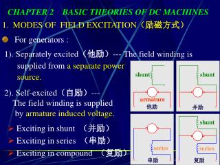
Electrical Machines DC machine AC machine Permanent Magnet Synchronous machine Induction machine Field Winding • Machines are called AC machines (generators or motors) if the electrical system is AC. • DC machines (generators or motors) if the electrical system is DC.
Two electromagnetic phenomena in the electric machines: Mutually perpendicular vectors • 1. Conductor moving in magnetic field - Motional voltage • Current carrying conductor in magnetic field - Electromagnetic force (Lorentz Force) • Both phenomena occur simultaneously in energy conversion process. Conductor moving in magnetic field Right-hand screw rule Current -carrying conductor moving in magnetic field Force direction
Electric Machines Construction • Stator and rotor ( ferromagnetic materials) • Slots with conductor • Cylindrical machine (a) uniform air gap • Salient pole machine (b) non uniform air gap • Iron core maximize flux density • Laminations reduce eddy current • Conductors interconnected to form windings • Armature winding in which voltage is induced • Field winding the one that produces the primary flux Structure of electrical machines
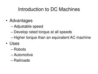
DC Machine Fundamentals • Generator action:An emf (voltage) is induced in a conductor if it moves through a magnetic field. • Motor action:A force is induced in a conductor that has a current going through it and placed in a magnetic field • Any DC machine can act either as a generator or as a motor.
DC Machine Fundamentals • DC Machine is most often used for a motor. • The major advantages of dc machines are the easy speed and torque regulation. • However, their application is limited to mills, mines and trains. As examples, trolleys and underground subway cars may use dc motors. • In the past, automobiles were equipped with dc dynamos to charge their batteries.
DC Machine Fundamentals • Even today the starter is a series dc motor • However, the recent development of power electronics has reduced the use of dc motors and generators. • The electronically controlled ac drives are gradually replacing the dc motor drives in factories. • Nevertheless, a large number of dc motors are still used by industry and several thousand are sold annually.
DC Machine • Variable speed, large and small power range • Field winding carrying DC-current in stator produces flux symmetrically distributed about pole axis = direct (d) axis • Armature winding in rotor Alternating voltage is induced • Mechanical commutator and brush assembly rectify the voltage to become DC. • Commutator-brush combination makes armature current distribution fixed in space • mmf of armature winding along quadratic (q) axis maximum torque , i.e at = 90 degree, Max. Torque produced at any time. Shift of brush position to change armature mmf 2-pole DC machine
DC Machines Construction • Stator: Stationary part of the machine. The stator carries a field winding that is used to produce the required magnetic field by DC excitation. Often know as the field. • Rotor: The rotor is the rotating part of the machine. The rotor carries a distributed winding, and is the winding where the emf is induced. Also known as the armature.
Commutator & Brushes Operation When the turn passes the interpolar region • End touch brush B1, current flows from a to b ( fig. a) • The turn is short-circuited (fig. b), voltage e12=0V • The current in the turn will reverse (fig. c) i.e. from b to a eab=b()2v
Armature Windings • Large machines have more than two poles most of the conductors are in region of high flux density • electrical degrees ed • • mechanical degrees md • • p number of poles • pole pitch = distance between centers of two adjacent poles =180oed • • coil pitch = distance between two sides of a coil • • full-pitch: coil pitch = pole pitch • • short-pitch: coil pitch < pole pitch (mainly in ac-machines)
Armature Windings - Lap winding • one coil between two adjacent commutator bars • 1/p of the total coils are connected in series • suitable for high-current low voltage number of parallel paths = a=number of poles = number of brushes
Armature Windings - Wave winding • p/2 coil connected in series between two adjacent commutator bars • suitable for high voltage low current • number of parallel paths = 2 • • number of brushes positions = 2 or more • • number of brushes is increased in large • machines to minimize the current density • In brushes.
Armature Windings - Voltage • the voltage induced in a turn • average value of the voltage induced in a turn • flux per pole Φ • induced voltage in the armature winding/parallel path • Ea independent of operation mode • in generator: generated voltage • in motor back emf • N number of turns in the armature winding • a number of parallel paths • Z total number of armature conductors • = 2N • machine constant, Ka
Armature Windings - Torque • the force on a conductor • the torque on a conductor • the average torque on a conductor • the total torque developed • power balance • machine constant
Example 1 • Q. A four pole dc machine has an armature of radius 15 cm and an effective length of 30 cm. The poles cover 75% of the armature periphery. The armature winding consists of 35 coils, each coil having seven turns. The coils are accommodated in 35 slots. The average flux density under each pole is 0.85 T. • If the armature is lap-wound, • Determine the armature constant Ka. • Determine the induced armature voltage when the armature rotates at 1000 rpm. • Determine the current in the coil and electromagnetic torque developed when the armature current is 400 A. • Determine the power developed by the armature. • r=15cm, l=30cm, N=35, slot=35, B=0.85. , p=4, w=1000 N(rpm)(2/60) rads-1 Sol_pg20 Sen Pg. 139
Example 2 If the dc machine armature in example 1 is wave-wound, repeat parts (a)-(d).
Magnetization • field mmf on d-axis • armature mmf on q-axis • no coupling (quadrature/decoupled mmf) • Magnetic core with infinite permeability at low values of flux (ampere-turns) • Assume material Ur infinite permeability, reluctance in airgap only. Magnetic flux/pole given as Cross-section view Equivalent circuit
Magnetization Curve • It is more convenient if the magnetization curve is expressed in terms of armature induce voltage Ea at a particular speed (Fig. a). • The magnetization curve obtained experimentally by rotating the dc machine at 1000 rpm and measuring the open-circuit armature terminal voltage as the current in the field winding is changed (Fig b). Represents the saturation level in the magnetic system of the dc machine for various values of the excitation mmf.
Magnetization Curve • increased Fp increased Φ saturation • Assume armature mmf has no effect • induced voltage in armature proportional to flux times speed (Ea m) Residual flux Flux - Fp (field mmf) relationship Open cct. Voltage Ea Field current, if
Classification of DC Machines • The field circuit and armature circuit can be interconnected in various ways to provide a wide variety of performance characteristics-an out standing advantage of dc machines. • The field poles can be excited by two field windings, a shunt filed winding and a series field winding. • The shunt winding has a large number of turns and takes only a small current (< 5% rated armature current). • The series winding has fewer turns but carries a large current. • If both windings are used, the series winding is wound on top of the shunt winding.
Classification of DC Machine (a) Separately excited machine (b) Series machine (c) Shunt machine (d) Compound machine Self-excited generator – need residual flux in machine iron * Permanent magnet can be considered as separately excited m/c., but constant excitation
Classification of DC Machines • Both shunt and series windings may be used , resulting in a compound machine. • If the shunt winding is connected across the armature, it is known as short-shunt machine. • In an alternative connection, the shunt winding is connected across the series connection of armature and series winding, and the machine is known as long-shunt machine. • A rheostat is inserted in field winding to control the field excitation ( vary mmf field)
Generators v-i characteristics Ea = IaRa + Va Va= Ea - IaRa V-I characteristics of DC generators
Example 3 • A lap-wound armature is used in a six-pole dc machine. There are 72 coils on the armature, each containing 12 turns. The flux per pole in the machine is 0.039 Wb and the machine spins at 400 rpm. Determine the induced voltage Ea. • Z = 2N = 2x72x12 =1728; Ka=Zp/(2a) • a = p = 6 • flux/pole = 0.039 • = 400 rpm=400(2)/60 • Ea=Ka..=449.28
Example 4 • A 12 pole dc generator a wave wound armature containing 144 coils of 10 turns each. The resistance of each turn is 0.011 ohm. Flux per pole is 0.05 Wb and it is running at a speed 200 rpm. Ea = ? T = ?