Download
1 / 42
460 likes | 819 Vues
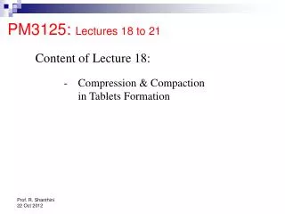
PM3125: Lectures 10 to 12. Content of Lectures 10 to 12: Heat transfer: Mathematical problems on heat transfer. Heat Exchanger in the industry. Shell-and-Tube Heat Exchanger. Heat Exchanger in the industry. Shell-and-Tube Heat Exchanger. Heat Exchanger in the industry.

E N D
PM3125: Lectures 10 to 12 • Content of Lectures 10 to 12: • Heat transfer: • Mathematical problems on heat transfer
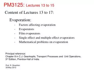
Heat Exchanger in the industry Shell-and-Tube Heat Exchanger
Heat Exchanger in the industry Shell-and-Tube Heat Exchanger
Heat Exchanger in the industry Shell-and-Tube Heat Exchanger
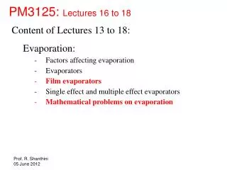
Heat Exchanger in the industry Shell Tubes Baffle Shell-and-Tube Heat Exchanger
Heat Exchanger in the industry Shell-and-Tube Heat Exchanger
Q = mc cc (Tc,out – Tc,in) = mh ch (Th,in – Th,out) Heat Exchanger Analysis Tc,in Th,out Th,in Tc,out . . .
Th,in Th,out Tc,out Tc,in Heat Exchanger Analysis Tc,in Parallel-flow heat exchanger Th,out Th,in Tc,out high heat transfer low heat transfer
Th,in Th,out Tc,out Tc,in Heat Exchanger Analysis – LMTD method Parallel-flow heat exchanger ΔTa ΔTb a b . Q = U A ΔTLM ΔTa - ΔTb is the log mean temperature difference (LMTD) where ΔTLM = ln(ΔTa / ΔTb)
Q = mc cc (Tc,out – Tc,in) = mh ch (Th,in – Th,out) Heat Exchanger Analysis Tc,out Counter-flow heat exchanger Th,out Th,in Tc,in . . .
Heat Exchanger Analysis Tc,out Counter-flow heat exchanger Th,out Th,in Th,in Tc,in Th,out Tc,out Tc,in
Th,in Th,out Tc,out Tc,in Heat Exchanger Analysis – LMTD method Counter-flow heat exchanger ΔTa ΔTb a b . Q = U A ΔTLM ΔTa - ΔTb is the log mean temperature difference (LMTD) where ΔTLM = ln(ΔTa / ΔTb)
Heat Exchanger Design – LMTD method An exhaust pipe, 75 mm outside diameter, is cooled by surrounding it by an annular space containing water. The hot gases enters the exhaust pipe at 350oC, gas flow rate being 200 kg/h, mean specific heat capacity at constant pressure 1.13 kJ/kg K, and comes out at 100oC. Water enters from the mains at 25oC, flow rate 1400 kg/h, mean specific heat capacity 4.19 kJ/kg K. The heat transfer coefficient for gases and water may be taken as 0.3 and 1.5 kW/m2 K and pipe thickness may be taken as negligible. Calculate the required pipe length for (i) parallel flow, and for (ii) counter flow.
Q = mc cc (Tc,out – Tc,in) = mh ch (Th,in – Th,out) Heat Exchanger Design – LMTD method Solution: . . . (1400 kg/hr) (4.19 kJ/kg K) (Tc,out – 25)oC = (200 kg/hr) (1.13 kJ/kg K) (350 – 100)oC The temperature of water at the outlet = Tc,out = 34.63oC.
Heat Exchanger Design – LMTD method Solution continued: • Parallel flow: ΔTa = 350 – 25 = 325oC ΔTb = 100 – 34.63 = 65.37oC ΔTa - ΔTb 325 – 65.37 ΔTLM = = 162oC = ln(ΔTa / ΔTb) ln(325 / 65.37) . = (UA) 162oC Q = U A ΔTLM What is UA?
Heat Exchanger Design – LMTD method Solution continued: 1/U = 1/hwater + 1/hgases = 1/1.5 + 1/0.3 = 4 (kW/m2 K)-1 Therefore, U = 0.25 kW/m2 K A = π (outer diameter) (L) = π (0.075 m) (L m) . = (UA) 162oC = (0.25) π (0.075) L (162) kW Q . What is Q?
Q = mc cc (Tc,out – Tc,in) = mh ch (Th,in – Th,out) Heat Exchanger Design – LMTD method Solution continued: . . . = (200 kg/h) (1.13 kJ/kg K) (350 – 100)oC = 15.69 kW Substituting the above in . = (0.25) π (0.075) L (162) kW = (UA) 162oC Q we get L = 1.64 m
Heat Exchanger Design – LMTD method (ii) Counter flow: Solution continued: ΔTa = 350 – 34.63 = 315.37oC ΔTb = 100 – 25 = 75oC ΔTa - ΔTb 315.37 – 75 ΔTLM = = 167.35oC = ln(ΔTa / ΔTb) ln(315.37 / 75) . = (UA) 167.35oC Q = U A ΔTLM . Q = 15.69 kW; U = 0.25 kW/m2 K ; A = π (0.075) L m2 Therefore, L = 1.59 m
Other Heat Exchanger Types Cross-flow heat exchanger with both fluids unmixed The direction of fluids are perpendicular to each other. In calculating the required surface area for this heat exchanger using LMTD method, a correction factor is applied on the LMTD. It lies between the required surface area for counter-flow and parallel-flow heat exchangers.
Cross-flow Heat Exchanger Analysis . ΔTLM = FΔTLM, counter flow Q = U A ΔTLM
Other Heat Exchanger Types In calculating the required surface area for this heat exchanger using LMTD method, a correction factor is applied on the LMTD. T1 T2 t2 t1 T2 t2 One shell pass and two tube passes t1 T1
Other Heat Exchanger Types Two shell passes and two tube passes Th,in Tc,in Tc,out Th,out In calculating the required surface area for this heat exchanger using LMTD method, a correction factor is applied on the LMTD.
Multi-pass Heat Exchanger Analysis See lecture notes provided separately.
Batch Sterilization (method of heating): Electrical heating Steam heating Direct steam sparging
For batch heating with constant rate heat flow: Total heat lost by the coil to the medium = heat gained by the medium M - mass of the medium T0 - initial temperature of the medium T - final temperature of the medium c - specific heat of the medium q - rate of heat transfer from the electrical coil to the medium t - duration of electrical heating . Electrical heating . q t = M c (T - T0)
For batch heating by direct steam sparging: M - initial mass of the raw medium T0 - initial temperature of the raw medium ms - steam mass flow rate t - duration of steam sparging H - enthalpy of steam relative to the enthalpy at the initial temperature of the raw medium (T0) T - final temperature of the mixture c - specific heat of medium and water . . . + M c T0 = (M + mst) c T (ms t) (H + cT0) Direct steam sparging . . = (M + ms t) c (T – T0) ms t H
For batch heating with isothermal heat source: M - mass of the medium T0 - initial temperature of the medium TH - temperature of heat source (steam) T - final temperature of the medium c - specific heat of the medium t - duration of steam heating U - overall heat transfer coefficient A - heat transfer area ( ) T0 - TH Steam heating U A t = M c ln T- TH Could you prove the above?
For batch heating with isothermal heat source: ( ) T0 - TH U A t = M c ln T- TH ( ) U A t T = TH + (T0 - TH) exp - c M Steam heating
Example of batch heating by direct steam sparging: A fermentor containing 40 m3 medium at 25oC is going to be sterilized by direct injection of saturated steam. The steam at 350 kPa absolute pressure is injected with a flow rate of 5000 kg/hr, which will be stopped when the medium temperature reaches 122oC. Determine the time taken to heat the medium. Additional data required: Enthalpy of saturated steam at 350 kPa = ?? Enthalpy of water at 25oC = ?? The heat capacity of the medium 4.187 kJ/kg.K The density of the medium are 4.187 kJ/kg.K and 1000 kg/m3, respectively.)
Example of batch heating by direct steam sparging: A fermentor containing 40 m3 medium at 25oC is going to be sterilized by direct injection of saturated steam. The steam at 350 kPa absolute pressure is injected with a flow rate of 5000 kg/hr, which will be stopped when the medium temperature reaches 122oC. Determine the time taken to heat the medium. Additional data: The enthalpy of saturated steam at 350 kPa and water at 25oC are 2732 and 105 kJ/kg, respectively. The heat capacity and density of the medium are 4.187 kJ/kg.K and 1000 kg/m3, respectively. Solution: Use the equation below: . . = (M + ms t) c (T – T0) ms t H
. . = (M + ms t) c (T – T0) ms t H (5000 kg/hr) (th) (2732-105) kJ/kg = [(40 m3)(1000 kg/m3) + (5000 kg/hr)(th)](4.187 kJ/kg.K)(122-25)K Taking the heating time (th) to be in hr, we get (5000 th) (2627) kJ = [40000 + 5000 t](4.187)(97)kJ (5000 th) [2627 – 4.187 x 97] = 40000 x 4.187 x 97 th = 1.463 hr Therefore, the time taken to heat the medium is 1.463 hours.
Example of batch heating with isothermal heat source: A fermentor containing 40 m3 medium at 25oC is going to be sterilized by an isothermal heat source, which is saturated steam at 350 kPa absolute pressure. Heating will be stopped when the medium temperature reaches 122oC. Determine the time taken to heat the medium. Additional data: The saturated temperature of steam at 350 kPa is 138.9oC. The heat capacity and density of the medium are 4.187 kJ/kg.K and 1000 kg/m3, respectively. U = 2500 kJ/hr.m2.K and A = 40 m2 Solution: Use the equation below: ( ) T0 - TH U A t = M c ln T- TH
( ) T0 - TH U A t = M c ln T- TH (2500 kJ/hr.m2.K) (40 m2) (tc) = (40 m3) (1000 kg/m3) (4.187 kJ/kg.K) ln[(25-138.9)/(122-138.9)] Taking the heating time (th) to be in hr, we get (2500 kJ/K) (40) (th) = (40) (1000) (4.187 kJ/K) ln[113.9/16.9] (2500 kJ/K) (40) (th) = (40) (1000) (4.187 kJ/K) (1.908) th = 3.1955 hr Therefore, the time taken to heat the medium is 3.1955 hours.
Explain why heating with isothermal heat source takes twice the time taken by heating with steam sparging, even though we used the same steam.
Questions from PM3125 / Feb 2010 past paper • 1) • What are the major differences between diffusion and convection? [5 marks] • What are the major differences among conduction, convection and radiation? [5 marks] 2) Briefly discuss the applications of the following laws. (a) Fourier’s law [2.5 marks] (b) Newton’s law of cooling [2.5 marks] (c) Stefan–Boltzmann Law [2.5 marks] (d) Fick’s law [2.5 marks]
Questions from PM3125 / Feb 2010 past paper • 8) A steel pipeline (inside diameter = 52.50 mm; outside diameter = 60.32 mm) contains saturated steam at 121.1oC. The line is insulated with 25.4 mm of asbestos. Assume that the inside surface temperature of the metal wall is at 121.1oC and the outer surface of the insulation is at 26.7oC. Taking the average value of ksteel as 45 W/m.K and that of kasbestos as 0.182 W/m.K, calculate the following: • (a) Heat loss for 30.5 m of pipe length. [10 marks] • (b) Mass (in kg) of steam condensed per hour in the pipe due to the heat loss. [10 marks] • Additional data given on the next slide:
Questions from PM3125 / Feb 2010 past paper Additional Data: i) Heat transfer rate through the pipe wall is given by, where L is the length of pipe, T1 and T2are the respective temperatures at the inner and outer surfaces of the insulated pipe, r1and r2 are the respective inner and outer radius of the steel pipe, and r3 is the outer radius of the insulated pipe. ii) Latent heat of vapourization of steam could be taken as 2200 kJ/kg.
Questions from PM3125 / Sept 2010 past paper • 1) A fermentor containing 40 m3 medium at 25oC is sterilized by an isothermal heat source, which is saturated steam at 4.5 bar absolute pressure. Determine the time taken to heat the medium to 122oC. [06 marks] • Additional Data: • - The density of the medium is 1000 kg/m3. • You may use the heat exchange equation • where U (= 695 W/m2.K) is the overall heat transfer coefficient, A (= 40 m2) is the heat transfer area, t is the time taken, M is the mass of the medium, c (= 4.187 kJ/kg.K) is the heat capacity of the medium, T0 is the initial temperature of the medium, T is the final temperature of the medium and TH is the temperature of the heat source. • - You may use the steam table (provided) if necessary.
Questions from PM3125 / Sept 2010 past paper • 2) Fluid A enters the shell-side of a shell-and-tube heat exchanger at a flow rate of 3.60 kg/s at 200oC and it leaves the heat exchanger at 150oC. Fluid B enters the tube-side of the exchanger at a flow rate of 2.88 kg/s at 100oC. Heat capacities of fluids A and B may be taken as 3.0 and 2.5 kJ/kg.K, respectively. • Show that fluid B leaves the heat exchanger at 175oC under the ideal conditions of no heat loss to the environment. [04 marks] • Should the heat exchanger be operated at parallel flow mode or at counter-current flow mode? Explain your answer. [04 marks] • c) Show that the log mean temperature driving force is about 36. [04 marks] • d) Determine the overall heat transfer area required assuming an overall heat transfer coefficient of 414 W/m2.K. [06 marks] • e) If the length of the tube-bundle of the heat exchanger is limited to 2 m, determine the number of 25 mm internal diameter tubes required to construct the tube-bundle. [04 marks]
Additional material not used in the lectures. . Q Critical Radius of Insulation To r Pipe Insulation ro Ti ri Ti – To = [ln(ro/ri)] /2πkPL + [ln(r/ro)] /2πkIL+ 1/hairA Pipe resistance could be neglected A = 2 π r L
Additional material not used in the lectures. . Q Critical Radius of Insulation Ti – To = [ln(r/ro)] /2πkIL+ 1/(hair 2πrL) 2π L ( Ti – To) = [ln(r/ro)] /kI+ 1/(hair r) Convective resistance Insulation resistance Increasing r increases insulation resistance and decreases heat transfer. Increasing r decreases convective resistance and increases heat transfer.
Additional material not used in the lectures. . Q Critical Radius of Insulation d /dr = 0 at the critical radius of insulation, which leads to rcr = kI / hair If the outer radius of the pipe (ro) < rcr and if insulation is added to the pipe, heat losses will first increase and go through a maximum at the insulation radius of rcr and then decrease. If the outer radius of the pipe (ro) > rcr and if insulation is added to the pipe, heat losses will continue to decrease.