Download
1 / 41
410 likes | 656 Vues
Knightro Kart. Liz Lyons Mike Scherban Oscar Orihuela. What Is Knightro Kart?. An interactive, Android controlled vehicle race system consisting of two independent cars and controllers. Vehicles are controlled by Android powered mobile devices or tablets

E N D
Knightro Kart Liz Lyons Mike Scherban Oscar Orihuela
What Is Knightro Kart? An interactive, Android controlled vehicle race system consisting of two independent cars and controllers. • Vehicles are controlled by Android powered mobile devices or tablets • Consists of two independent vehicles, a track utilizing infrared, and two independent remote controls
Remote Control Mobile device will be used in landscape mode. It will utilize hardware level sensor data, and interpret them to tell the MSP430 how to direct the vehicle.
Why Android? • Essentially Free – No new hardware costs, free SDK, familiar languages • Open source platform, easy to learn
Target APIs 10 (Android 2.3.3 Gingerbread and higher), approximately 88.2% of Android market
Target APIs 10 (Android 2.3.3 Gingerbread and higher), approximately 88.2% of Android market
Remote Control Requirements Android Device Must: • Have Bluetooth Capability • Contain Accelerometer Sensors • Have Touch Screen • Run Android 2.3.3 Gingerbread or newer OS
Handling Accelerometers Accelerometers are seen by the devices relative to an imagined coordinate system. • We will be using the Y (left/right) and Z (forward/back) axis values to control the cars.
Handling Accelerometers Must apply low-pass filter to isolate gravity, and then a high-pass filter to remove gravity from the readings. Also helps to smooth out values.
Connecting Android devices will be able to connect to one and only one car. • Will use received values from the MSP430 to enhance UI with more info such as vehicle speed and current lap.
Bluetooth Remote control application sends information to the MSP 430 via Bluetooth. • Sends one byte at a time, byte value depends on accelerometer values
Bluetooth Module • Roving Networks RN-41 • Minimal configuration • Baud rate • Built in antenna • Automatically pushes data via UART RX/TX pins • Runs own Bluetooth stack • Low power • 30 mA connected • 3.3V • 100m range
Microcontroller 2.75” 2.75”
Microcontroller • Same voltage as Bluetooth module • More feature rich IDE • No special bootloaders required
Programming and Debugging • JTAG used to take advantage of viewable registers and memory locations, and disassembly • Connect through TI USB FET device
Motor Signals • Takes advantage of MSP430 hardware PWM support • PWM used to add variable speed Slow Fast!
Microcontroller Comm. • 9600 Baudrate • RX/TX between BT and MSP430 crossed • Interrupts will be used for phone MSP430 and infrared signal
Low Power Mode • Bluetooth Module separate from MSP430 • Allows BT pairing while MSP430 is asleep • MSP430 goes to sleep at power on and when not in race mode • Turns off clocks • Button on the car or command from phone will wake the car for use
Printed Circuit Board • Most components will be on a custom printed circuit board designed in Eagle
Printed Circuit Board BT Module and status LEDs LEDs JTAG Power MSP430
Track • Race car will contain an IR phototransistor • Biased by IR light • At the START line for the Race Track, there will be a line of IR LEDs that will set off IR phototransistor • By setting off the IR phototransistor on the car, it will allow user to know how many laps the car has travelled during the race
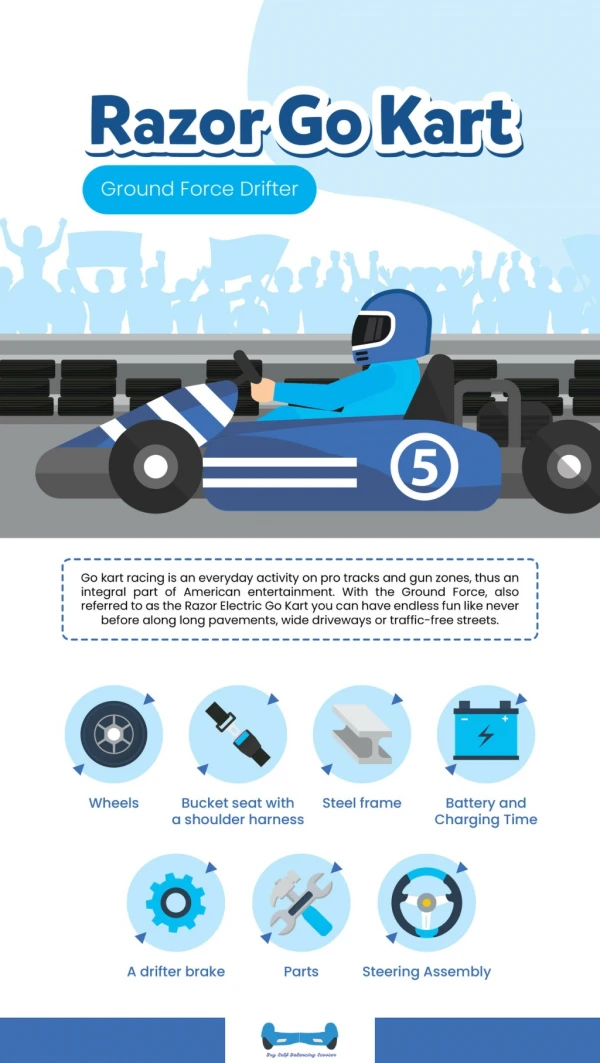
Race Car • 9v power supplyrequired • Potential to travel20 mph • 2 D.C motors • 1st Motor controlling FWD & REV motion • 2nd Motor controlling turning Left & Right • 17 inches Long • 7 inches Wide • 8 Inches Tall
H-Bridge • Serves as mediator between MSP430 & Race car motors • MSP430 will receive commands from Mobile Application and send high / low signals to the H-bridge connected to the motors causing the motors to spin in a certain direction • EX: Clockwise / Counter-clockwise / Stand Still
H-Bridge - Typical • Typical H-Bridge configuration • Inner Circle = Motor • Switches represent Transistors • Motor is at a stand still
H-Bridge - Clockwise • Due to the directional flowof the circuit, the H-bridgeis causing the D.C Motor connected to it to spinclockwise
H-Bridge – counter clockwise • Due to the directional flowof the circuit, the H-bridgeis causing the D.C Motor connected to it to spincounter-clockwise
SN754410 • H-Bridge Designed to drive inductive loads such as DC Motors • Chosen for its capability to manageboth D.C Motors in a single chip • Manufacturer: Texas Instruments • Cost: $2.16 • 1 Chip per car needed • . • .
D.C Motor VS Servo Motor • Race car will require 2 motors • 1st Motor controls – FWD & REV motion – D.C Motor • 2nd Motor Controls – turning capabilities • For the purpose of Knightro Kart, D.C motors will be sufficient as well as better for our wallets & Handbag
Desirables • Speedometer • Phone to Phone Communication • Race Standing Notifications
Magnetic Reed Switch • Switch opens at close proximityof a magnet • Sends PWM signal back to MSP430 • Switch will be attached to axelof Race car • Low power magnet will be attached to rim or inner wheel of the race car
Budget and Financing to Date Total Cost To Date: $364.60
Plans For Completion • Complete Soldering • Complete Code • Assemble Vehicles • Test • Construct IR Start Line