Download
1 / 85
980 likes | 1.56k Vues
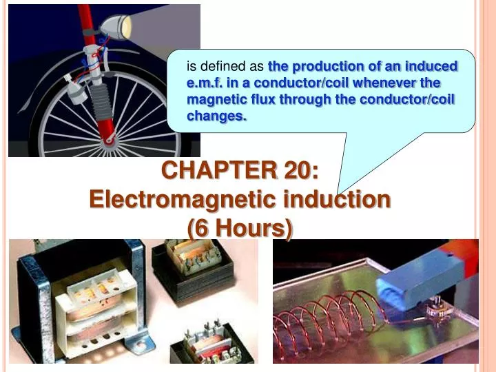
is defined as the production of an induced e.m.f . in a conductor/coil whenever the magnetic flux through the conductor/coil changes. CHAPTER 20: Electromagnetic induction (6 Hours). Learning Outcome:. 20.1 Magnetic flux ( 1/2 hour).

E N D
is definedasthe production of an induced e.m.f. in a conductor/coil whenever the magnetic flux through the conductor/coil changes. CHAPTER 20: Electromagnetic induction(6 Hours)
Learning Outcome: 20.1 Magnetic flux (1/2 hour) At the end of this chapter, students should be able to: • Define and use magnetic flux,
(7.1) 20.1.1 Magnetic flux of a uniform magnetic field • is defined as the scalar product between the magnetic flux density, B with the vector of the area, A. Mathematically, where
area • It is a scalar quantity and its unit is weber (Wb) OR tesla meter squared ( T m2). • Consider a uniform magnetic field B passing through a surface area A of a single turn coil as shown in Figures 7.2a and 7.2b. • From the Figure 7.2a, the angle is 0 thus the magnetic flux is given by Figure 7.2a maximum
area Note: • From the Figure 7.2a, the angle is 90 thus the magnetic flux is given by Figure 7.2b • Direction of vector A always perpendicular (normal) to the surface area, A. • The magnetic flux is proportional to the number of field lines passing through the area.
N S R Q S P Example 1 : A single turn of rectangular coil of sides 10 cm 5.0 cm is placed between north and south poles of a permanent magnet. Initially, the plane of the coil is parallel to the magnetic field as shown in Figure 7.3. If the coil is turned by 90 about its rotation axis and the magnitude of magnetic flux density is 1.5 T, Calculate the change in the magnetic flux through the coil. Figure 7.3
Solution : The area of the coil is Initially, Finally, Therefore the change in magnetic flux through the coil is From the figure, = thus the initial magnetic flux through the coil is From the figure, = thus the final magnetic flux through the coil is
Example 2 : A single turn of circular coil with a diameter of 3.0 cm is placed in the uniform magnetic field. The plane of the coil makes an angle 30 to the direction of the magnetic field. If the magnetic flux through the area of the coil is 1.20 mWb, calculate the magnitude of the magnetic field. Solution : The area of the coil is
Solution : The angle between the direction of magnetic field, B and vector of area, A is given by Therefore the magnitude of the magnetic field is
Learning Outcome: 20.2 Induced emf (2 hours) At the end of this chapter, students should be able to: • Use Faraday's experiment to explain induced emf. • State Faraday’s law and Lenz’s law to determine the direction of induced current. • Apply formulae, • Derive and use induced emf: I) in straight conductor, ii) in coil, OR iii) in rotating coil,
No movement 20.2.1 Magnetic flux 20.1.1(a) Phenomenon of electromagnetic induction • Consider some experiments were conducted by Michael Faraday that led to the discovery of the Faraday’s law of induction as shown in Figures 7.1a, 7.1b, 7.1c, 7.1d and 7.1e. Figure 7.1a
Move towards the coil No movement S N Figure 7.1b Figure 7.1c
Move away from the coil Move towards the coil N S Figure 7.1d S N Figure 7.1e
From the experiments: • When the bar magnet is stationary, the galvanometer not show any deflection (no current flows in the coil). • When the bar magnet is moved relatively towards the coil, the galvanometer shows a momentary deflection to the right (Figure 7.1b). When the bar magnet is moved relatively away from the coil, the galvanometer is seen to deflect in the opposite direction (Figure 7.1d). • Therefore when there is any relative motion between the coil and the bar magnet , the current known as induced current will flow momentarily through the galvanometer. This current due to an induced e.m.f across the coil. • Conclusion : • When the magnetic field lines through a coil changes thus the induced emf will exist across the coil.
v increases induced emf increases • The magnitude of the induced e.m.f. depends on the speed of the relative motion where if the Therefore v is proportional to the induced emf. v decreases induced emf decreases
Example 3 : Figure 7.4 The three loops of wire as shown in Figure 7.4 are all in a region of space with a uniform magnetic field. Loop 1 swings back and forth as the bob on a simple pendulum. Loop 2 rotates about a vertical axis and loop 3 oscillates vertically on the end of a spring. Which loop or loops have a magnetic flux that changes with time? Explain your answer.
(7.2) 20.2.2 Induced emf 20.2.2(a) Faraday’s law of electromagneticinduction • states that the magnitude of the induced emf is proportional to the rate of change of the magnetic flux. Mathematically, • The negative sign indicates that the direction of induced emf always oppose the change of magnetic flux producing it (Lenz’s law). OR where
(7.3) (7.4) , then eq. (7.3) can be written as where and
(7.5) (7.6) • For a coil of N turns is placed in a uniform magnetic field B but changing in the coil’s area A, the induced emf is given by and
(7.7) Note: the induced current I is given by • For a coil is connected in series to a resistor of resistance R and the induced emf exist in the coil as shown in Figure 7.5, and Figure 7.5 • To calculate the magnitude of induced emf, the negative sign can be ignored. • For a coil of N turns, each turn will has a magnetic flux of BAcos through it, therefore the magnetic flux linkage (refer to the combined amount of flux through all the turns) is given by
Example 4 : The magnetic flux passing through a single turn of a coil is increased quickly but steadily at a rate of 5.0102Wb s1. If the coil have 500 turns, calculate the magnitude of the induced emf in the coil. Solution : By applying the Faraday’s law equation for a coil of N turns , thus
Example 5 : A coil having an area of 8.0 cm2 and 50 turns lies perpendicular to a magnetic field of 0.20 T. If the magnetic flux density is steadily reduced to zero, taking 0.50 s, determine a. the initial magnetic flux linkage. b. the induced emf. Solution : a. The initial magnetic flux linkage is given by
Solution : a. b. The induced emf is given by
Example 6 : A narrow coil of 10 turns and diameter of 4.0 cm is placed perpendicular to a uniform magnetic field of 1.20 T. After 0.25 s, the diameter of the coil is increased to 5.3 cm. a. Calculate the change in the area of the coil. b. If the coil has a resistance of 2.4 , determine the induced current in the coil. Solution : Initial Final
Solution : a. The change in the area of the coil is given by
Solution : b. Given The induced emf in the coil is Therefore the induced current in the coil is given by
North pole 20.2.2 (b) Lenz’s law • states that an induced electric current always flows in such a direction that it opposes the change producing it. • This law is essentially a form of the law of conservation of energy. • An illustration of lenz’s law can be explained by the following experiments. Direction of induced current – Right hand grip rule. 1st experiment: • In Figure 7.6 the magnitude of the magnetic field at the solenoid increases as the bar magnet is moved towards it. • An emf is induced in the solenoid and the galvanometer indicates that a current is flowing. N Figure 7.6
Q X X X X X X X X X X X X X X X X X X X X X X X X X X X X X X X X X X X X X X X X X X X X X X X X P • To determine the direction of the current through the galvanometer which corresponds to a deflection in a particular sense, then the current through the solenoid seen is in the direction that make the solenoid upper end becomes a north pole. This opposes the motion of the bar magnet and obey the lenz’s law. 2nd experiment: • Consider a straight conductor PQ is placed perpendicular to the magnetic field and move the conductor to the left with constant velocity v as shown in Figure 7.7. • When the conductor move to the left thus the induced current needs to flow in such a way to oppose the change which has induced it based on lenz’s law. Hence galvanometer shows a deflection. Figure 7.7
Note: • To determine the direction of the induced current (induced emf) flows in the conductor PQ, the Fleming’s right hand (Dynamo) rule is used as shown in Figure 7.8. • Therefore the induced current flows from Q to P as shown in Figure 7.7. • Since the induced current flows in the conductor PQ and is placed in the magnetic field then this conductor will experience magnetic force. • Its direction is in the opposite direction of the motion. Thumb – direction of Motion First finger – direction of Field Second finger – direction of induced current OR induced emf Figure 7.8
S N N S - + Q P 3rd experiment: • Consider two solenoids P and Q arranged coaxially closed to each other as shown in Figure 7.9a. • At the moment when the switch S is closed, current I begins to flow in the solenoid P and producing a magnetic field inside the solenoid P. Suppose that the field points towards the solenoid Q. Figure 7.9a
S N N S + - P Q • The magnetic flux through the solenoid Q increases with time. According to Faraday’s law ,an induced current due to induced emf will exist in solenoid Q. • The induced current flows in solenoid Q must produce a magnetic field that oppose the change producing it (increase in flux). Hence based on Lenz’s law, the induced current flows in circuit consists of solenoid Q is anticlockwise (Figure 7.9a) and the galvanometer shows a deflection. Figure 7.9b
At the moment when the switch S is opened, the current I starts to decrease in the solenoid P and magnetic flux through the solenoid Q decreases with time. According to Faraday’s law ,an induced current due to induced emf will exist in solenoid Q. • The induced current flows in solenoid Q must produce a magnetic field that oppose the change producing it (decrease in flux). Hence based on Lenz’s law, the induced current flows in circuit consists of solenoid Q is clockwise (Figure 7.9b) and the galvanometer seen to deflect in the opposite direction of Figure 7.9a.
Example 7 : A single turn of circular shaped coil has a resistance of 20 and an area of 7.0 cm2. It moves toward the north pole of a bar magnet as shown in Figure 7.10. If the average rate of change of magnetic flux density through the coil is 0.55 T s1, a. determine the induced current in the coil b. state the direction of the induced current observed by the observer shown in Figure 7.10. Figure 7.10
Solution : a. By applying the Faraday’s law of induction, thus Therefore the induced current in the coil is given by
Solution : b. Based on the lenz’s law, hence the direction of induced current is clockwise as shown in figure below.
P X X X X X X X X X X X X X X X X X X X X X X X X X X X X X X X X X X X X X X X X X X X X Q X X X X 20.2.3 Induced emf in a straight conductor • Consider a straight conductor PQ of length l is moved perpendicular with velocity v across a uniform magnetic field B as shown in Figure 7.11. • When the conductor moves through a distance x in time t, the area swept out by the conductor is given by Area, A Figure 7.11
(7.8) • Since the motion of the conductor is perpendicular to the magnetic field B hence the magnetic flux cutting by the conductor is given by • According to Faraday’s law, the emf is induced in the conductor and its magnitude is given by and and
(7.9) Note: (7.10) • In general, the magnitude of the induced emf in the straight conductor is given by • This type of induced emf is known as motional induced emf. • The direction of the induced current or induced emf in the straight conductor can be determined by using the Fleming’s right hand rule (based on Lenz’s law). • In the case of Figure 7.11, the direction of the induced current or induced emf is from Q to P. Therefore P is higher potential than Q. where • Eq. (7.9) also can be used for a single turn of rectangular coil moves across the uniform magnetic field. • For a rectangular coil of N turns,
C D Example 8 : A 20 cm long metal rod CD is moved at speed of 25 m s1 across a uniform magnetic field of flux density 250 mT. The motion of the rod is perpendicular to the magnetic field as shown in Figure 7.12. a. Calculate the motional induced emf in the rod. b. If the rod is connected in series to the resistor of resistance 15 , determine i. the induced current and its direction. ii. the total charge passing through the resistor in two minute. Figure 7.12
Solution : a. By applying the equation for motional induced emf, thus b. Given i. By applying the Ohm’s law, thus By using the Fleming’s right hand rule, ii. Given The total charge passing through the resistor is given by
S N coil 20.2.4 Induced emf in a rotating coil • Consider a rectangular coil of N turns, each of area A, being rotated mechanically with a constant angular velocity in a uniform magnetic field of flux density B about an axis as shown in Figure 7.13. • When the vector of area, A is at an angle to the magnetic field B,the magnetic flux through each turn of the coil is given by Figure 7.13: side view and
(7.11) (7.12) • By applying the equation of Faraday’s law for a coil of N turns, thus the induced emf is given by • The induced emf is maximum when hence where where
(7.13) Note: where • Eq. (7.11) also can be written as • Conclusion : A coil rotating with constant angular velocity in a uniform magnetic field produces a sinusoidally alternating emf as shown by the induced emf against time t graph in Figure 7.14. This phenomenon was the important part in the development of the electric generator or dynamo. Figure 7.14
Example 9 : A rectangular coil of 100 turns has a dimension of 10 cm 15 cm. It rotates at a constant angular velocity of 200 rpm in a uniform magnetic field of flux density 5.0 T. Calculate a. the maximum emf produced by the coil, b. the induced emf at the instant when the plane of the coil makes an angle of 38 to the magnetic field. Solution : The area of the coil is and the constant angular velocity in rad s1 is
Solution : a. The maximum emf produced by the coil is given by b. From the figure, the angle is Therefore the induced emf is given by
Exercise 20.1 : 1. A bar magnet is held above a loop of wire in a horizontal plane, as shown in Figure 7.15. The south end of the magnet is toward the loop of the wire. The magnet is dropped toward the loop. Determine the direction of the current through the resistor a. while the magnet falling toward the loop, b. after the magnet has passed through the loop and moves away from it. (Physics for scientists and engineers,6th edition, Serway&Jewett, Q15, p.991) ANS. : U think Figure 7.15
2. A straight conductor of length 20 cm moves in a uniform magnetic field of flux density 20 mT at a constant speed of 10 m s-1. The velocity makes an angle 30 to the field but the conductor is perpendicular to the field. Determine the induced emf. ANS. : 2.0102 V 3. A coil of area 0.100 m2 is rotating at 60.0 rev s-1 with the axis of rotation perpendicular to a 0.200 T magnetic field. a. If the coil has 1000 turns, determine the maximum emf generated in it. b. What is the orientation of the coil with respect to the magnetic field when the maximum induced emf occurs? (Physics for scientists and engineers,6thedition,Serway&Jewett, Q35, p.996) ANS. : 7.54103 V 4. A circular coil has 50 turns and diameter 1.0 cm. It rotates at a constant angular velocity of 25 rev s1 in a uniform magnetic field of flux density 50 T. Determine the induced emf when the plane of the coil makes an angle 55 to the magnetic field. ANS. : 1.77105 V
Learning Outcome: 20.3 Self-inductance (1 hour) At the end of this chapter, students should be able to: • Define self-inductance. • Apply formulae for a loop and solenoid.
S N R S 20.3 Self-inductance 20.3.1 Self-induction • Consider a solenoid which is connected to a battery , a switch S and variable resistor R, forming an open circuit as shown in Figure 7.16a. • When the switch S is closed, a current I begins to flow in the solenoid. • The current produces a magnetic field whose field lines through the solenoid and generate the magnetic flux linkage. • If the resistance of the variable resistor changes, thus the current flows in the solenoid also changed, then so too does magnetic flux linkage. Figure 7.16a: initial