Download
1 / 1
10 likes | 122 Vues
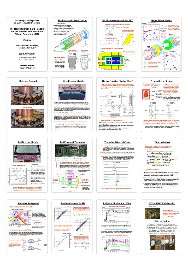
The Backward Silicon Tracker. DIS Measurements with the BST. Heavy Flavor Physics. 10 th European Symposium on Semiconductor Detectors. Applications:. Inelastic eP-scattering cross-section:. Acceptance for heavy quarks with the FST and BST Q 2 ~ (5…400 ) GeV 2.

E N D
The Backward Silicon Tracker DIS Measurements with the BST Heavy Flavor Physics 10th European Symposium on Semiconductor Detectors Applications: Inelastic eP-scattering cross-section: Acceptance for heavy quarks with the FST and BST Q2 ~ (5…400 ) GeV2 • Track trigger for an efficient use • of the high luminosity of HERA-II The New Radiation-hard Readout for the Forward and Backward Silicon Detectors of H1 • Track curvature measurement and the • particle’s momentum determination BST acceptance in the x, Q2 kinematical plane • Z-vertex reconstruction and • rejection of non-eP tracks • and other background Event kinematics: I.Tsurin University of Antwerpen, on behalf of DESY Deeply Inelastic Scattering event Strip detector (640 readout strips) Pad detector (32 pads) Inclusive measurements of a scattered electron with a calorimeter and the BST: Address: Notkestrasse 85, 22607 Hamburg, Germany. E-mail: tsurin@mail.desy.de Detector system Phone: +49-40-8998-4598 • 144 strip detectors • (number of readout • channels = 92.160) • 48 pad detectors • (number of trigger • channels = 1536) measurements (2…10)% in extended x range Wildbad Kreuth June 12-16, 2005 measurements with high luminosity Detectors Assembly Strip Detector Module The new “Analog Pipeline Chip” Preamplifier’s Circuitry Ring-shaped P-FET from the “PSI_025V2_core” library The APC128 readout chip and its decoder were re-designed in collaboration between DESY, PSI (Villigen, Switzerland) and KIP (Heidelberg, Germany) and manufactured in 0.25 um process by UMC (Taiwan). Strip detectors P-FET transistors enclosed in the N-well are better isolated from the P-substrate leakage currents. Their usage in the preamplifier’s feedback cir-cuitry requires negative bias voltages with respect to the signal ground. To prevent high stress current density during plasma exposure the gate voltage must be always above the substrate potential * The strip pitch = 25 µm, the readout pitch = 75 µm (every third strip has an analog readout). The charge sharing between intermediate and readout strips allows for a precise coordinate measurement: hit residuals for tracks 10-15 µm. A serial readout of two detectors (2 x 640) strips with 1 µs / channel requires 1.3 ms for the data processing with a continuously cycling acquisition program (sequencer code). The APC settings are reloaded regularly making the readout rather stable against single event upsets. Pad detectors The old APC128 SACMOS radiation damage studies* A cumulative dose above 100 kRad is responsible for the pedestal and hence readout amplitude lowering. This effect is attributed to the bulk leakage current at the preamplifier's input. The influence of impurities trapped in the silicon onto signal could be parameterized and investigated in the ASIC design package with an equivalent current source. APC128 UMC.25 specifications: The signal ground is separated from the substrate and the operating (.) of the push-pull cascade is shifted by +0.6 V. Now the gate voltage of the feedback transistors could be selected in the range (0…+0.6) V. Front-end functions (less critical to the choice of components): • 128 channels, each containing an analog pipeline with a depth of • 32 storage capacitors • ENC (1σ) 400±100 e (the switching noise has a large contribution) • Shaping time constant 1.5±0.3µs • Minimum sensitivity 5±1 mV/fC; the signal amplification and • processing is possible by sequencer code Signal buffering, Clock distribution, Supply regeneration * “Plasma-charging damage in ultra-thin gate oxide”, Kin P. Cheung, Microelectronics Reliability 40 (2000), pp. 1981-1986. * “Development of a radiation hard version of the Analog Pipeline Chip APC128”, M. Hilgers, R. Horisberger, Nucl. Instr. Meth. NIM A481 (2002) pp. 556-565. Pad Detector Module Pad Front-end Electronics The online Trigger Software Design Outlook Single event upsetmay force a trigger signal. The coincidence with other H1 sub-detectors (SPACAL, Veto counters etc.) reduces a risk of a false trigger. All signal conditions and relations are synchronized to the clock frequency to protect the trigger algorithm against random data changes. Commercial components preserving general functionality with the total ionizing dose up to 3.2 MRad: • Field programmable gate arrays (ALTERA): • EP20K300EQC240, EP1K30TC144 • Fast comparators (MAXIM): MAX964EEE • Opto-couplers (Agilent): HCPL-0731 • Low dropout voltage regulators (Nat. Semicond.): • LM3965ES, LM2991S, LM1117MP, LM1086CS • Amplifiers (Analog Devices): AD8554AR • Reference (Analog Devices): AD589JR • Differential transmitters / receivers (Texas): • AM26LV31CD, AM26LV32CD Memory bit flips were crucial for the frequent trigger masks, therefore the predefined track patterns were coded as combinatorial logics. Single event latch-up can freeze data bits distorting the trigger patterns. A self-latch scheme for input signals with a common reset is utilized to avoid combinations with permanent "1". Mask permutations are written to compensate for stuck signals or inefficient pads. The front-end boards for the detector control and the trigger data processing (ALTERA chip EP20K300E is the core of each board): • Specifications: • 32 channels with digital and • analog outputs with controlled • ON / OFF function and internal • or external trigger thresholds • Individual mode / subtraction • of neighboring channels for the • common mode suppression • Dynamic input range 35±1 dB • Controlled gain 15…30 mV / fC • ENC (1σ) 600±100 e • Noise slope 15±5 e / pF • Shaping time constant 30±1 ns • Has a calibration pulse mode PRO/A readout chip • Manipulating the PRO/A steering codes, setting trigger thresholds • Synchronization of all detector pulses to HERA clock frequency • Track validation with masks and computing of the track topology • Accumulating and transmitting of raw data from the silicon pads Operation experience: • Monitoring the multiplicity • of triggered pads 1. Analog circuits should have 100% feedback, i.e. voltage repeaters must be used rather than amplifiers. In any case the digital circuitry is preferable because it operates with two robust levels. 2. As much functionality as possible should be implemented into the program algorithm. It is always easier to recompile the design acti- vating new FPGA resources than to repair the hardware. 3. To ensure a reliable operation in the environment with radiation load a steady HERA background control and a fast response on radiation effects in the silicon are very important to keep the exposure rate below 10 kRad/year. • Monitoring the radiation • background Detector Modules Interface to the H1 DAQ 96 channels 384 channels Auxiliary functions: The PRO/A readout chip was designed in collaboration between DESY Zeuthen and IDE AS (Oslo, Norway) and manufactured in 1.2 µm N-well CMOS process by AMS. • Temperature • measurements • with a CAN chip. Soft failures are resolved by the front-end reinitializing Radiation Monitor for H1 Radiation Background Radiation Monitor for HERA FST and BST Collaboration Intense background components: Reaction to the beam currents • DESY Zeuthen The radiation monitor rate depends on the vacuum in HERA, therefore for the given conditions the background can be predicted in the first approxi- mation from the current product: • Synchrotron radiation: • DESY Hamburg • Prague Charles University • Institute of Physics AS CR • Rutherford Appleton • Laboratory The synchrotron radiation fan does not enter the H1 facility directly but some part of it scatters from absorbers to- wards the detector and does heat the beam line optics that causes a gas evaporation and worsens the vacuum. In turn this increases a Detector Smiths • e-gas scattering • P-gas scattering Max Klein Peter Kostka Thomas NaumannJan Kretzschmar Tomas Lastovicka Mirek NozickaWolfgang Lange Hans Henschel Joachim MeiβnerRainer Wallny Doris Eckstein Vladimir ArkadovMilan Janata Ulrich Harder Wolfgang EickWolfgang Philipp Olaf Gräber Ilya TsurinSergey Gorbunov Bill Haynes H.-C.S-C. A linear correlation between the radiation monitor rate and the ionization current in the central trackers is used for chambers to control their “turn on” conditions to prevent their high voltage trips. The instantaneous count rate can be helpful for the HERA crew as a feedback from the detector during injection and the beam steering: http://h1lumiserver.desy.de:8080/main/h1mon.html In coincidence with some other counters the radiation monitor can be used for an automatic beam dump in a case of severe radiation load. where the latter is the main background component. Dose rate measurement with Pads The trigger algorithm of the pad detector was extended to monitor online the particle flux through the silicon. The multiplicities of triggered pads are summed up within 1 second, during the next second the result obtained is sent out while the next integral is being prepared. Correlation with scintillation counter rates Measuring the cumulative dose becomes possible with silicon detectors (besides beam losses when the energy is released in a very short time) as all particles deposit on average the same energy One silicon sensor (20 cm2) is taken as an area unit for the radiation monitor. The maximum rate over 48 pad detector modules is being displayed.