Download

1 / 37
370 likes | 534 Vues
Laser Controller One (LC1). A.R. Hertneky J.W. O’Brien J.T. Shin C.S. Wessels. www.teamvice.net. Outline. Background Architecture and parts Interfaces Circuit/logic design Updated schedule & responsibilities. Laser Controller One (LC1). Interacts with laser analog control system

E N D
Laser Controller One (LC1) A.R. Hertneky J.W. O’Brien J.T. Shin C.S. Wessels www.teamvice.net
Outline • Background • Architecture and parts • Interfaces • Circuit/logic design • Updated schedule & responsibilities Critical Design Review (CDR)
Laser Controller One (LC1) • Interacts with laser analog control system • Consists of rack-mountable enclosure with connections to external devices • Will manage laser system to establish and maintain frequency lock Critical Design Review (CDR)
Analog signals f0 • Saturated absorption spectroscopy (sat spec) raw signal is subject to high-pass filtering • Derivatives can still be generated using a mixer • Use sat spec (f0) to update LCD • Use first derivative (f1) to locate peaks • Use second derivative (f2) to monitor lock f1 f2 Critical Design Review (CDR)
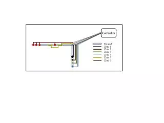
System Environment Block Diagram Critical Design Review (CDR)
Microprocessor Freescale M68EC020 Microprocessor • Clock speed for… • wire wrapped prototype: 12MHz • PCB integration: 25MHz • 32-bit data/24-bit address • Dynamic bus sizing • Instruction cache • 100-QFP package Critical Design Review (CDR)
Data Flow Block Diagram Critical Design Review (CDR)
Memory Map Critical Design Review (CDR)
Control Flow Block Diagram Critical Design Review (CDR)
Interrupt Priorities Critical Design Review (CDR)
CPLD Block Diagram Critical Design Review (CDR)
Wire Wrap Prototype Preview clock/reset CPU CPLD UARTs/drivers SRAM Flash (x1) Headers for FPGA Critical Design Review (CDR)
Schematic: CPU Critical Design Review (CDR)
Schematic: FPGA Critical Design Review (CDR)
Schematic: Memory Critical Design Review (CDR)
Schematic: UARTs Critical Design Review (CDR)
Schematic: Keypad Critical Design Review (CDR)
Schematic: RS-232 Drivers Critical Design Review (CDR)
Schematic: LEDs Critical Design Review (CDR)
Schematic: Shaft Encoder Critical Design Review (CDR)
Schematic: Reset Circuit Critical Design Review (CDR)
8 Channel/12 Bit Serial ADC - AD7890 Critical Design Review (CDR)
AD7890 A/D: Interfaces Critical Design Review (CDR)
AD7890 A/D: Control Register Critical Design Review (CDR)
AD7890 A/D: Timing Diagram Critical Design Review (CDR)
Dual 12-Bit Serial DACPORT-AD7249 Critical Design Review (CDR)
AD7249 D/A Interfaces Critical Design Review (CDR)
AD7890 D/A: Timing Diagram Critical Design Review (CDR)
Software Architecture • Message passing & synchronization will take place through circular buffers (CBs) • Interrupt service routines (ISRs) will insert data in CBs • Main program will setup hardware, and then begin checking for/acting on messages in CBs Critical Design Review (CDR)
Event ISRs CBs Software Flow Diagram LCD Driver UI Manager Main Program Loop Laser Manager FPGA Critical Design Review (CDR)
UI Mock-up Critical Design Review (CDR)
Updated Schedule Critical Design Review (CDR)
Milestone I Deliverables (3/21) • FPGA • sample/store and drive all analog signals • Wire wrap prototype • running boot loader & minimal system • talk to all peripherals • PCB • rev 1 populated and testing • Enclosure • fully specified and drafted Critical Design Review (CDR)
Milestone II Deliverables (4/18) • FPGA • can establish laser lock • lock monitor/recovery in alpha stage • full communication with PCB/CPU • PCB • rev 2 debugged and running • ready for rev 3 if necessary • Draft of user and technical manuals Critical Design Review (CDR)
Expo Deliverables (5/4) • System • user can lock laser manually or by computer • will detect and recover from broken lock • Form factor • enclosure is ready to be installed in client lab • Documentation • completed user manual and technical manual Critical Design Review (CDR)
Project Responsibilities • A.R. Hertneky • PCB layout, FPGA development, laser system modifications, user manual • J.W. O’Brien • System-level architecture/software, chassis/UI design, test procedure design, CPLD development, technical manual • J.T. Shin • Analog interfaces, FPGA on-chip peripherals, peripheral simulation, technical manual • C.S. Wessels • Graphical LCD driver, FPGA development, boot loader and CPU firmware, user manual Critical Design Review (CDR)
Thank you. Questions? “I don’t know; and when I know nothing, I usually hold my tongue.” – Creon in Oedipus the King Critical Design Review (CDR)