Download
1 / 36
360 likes | 579 Vues
Lecture 4: Quenching and Cryogenics. Plan the quench process decay times and temperature rise propagation of the resistive zone computing resistance growth and decay times quench protection schemes. the most likely cause of death for a superconducting magnet. cryogenic fluids

E N D
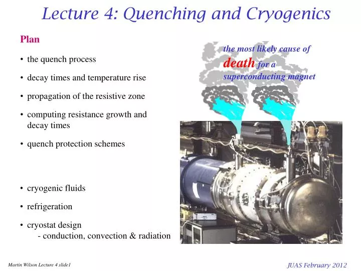
Lecture 4: Quenching and Cryogenics • Plan • the quench process • decay times and temperature rise • propagation of the resistive zone • computing resistance growth and decay times • quench protection schemes the most likely cause of deathfor a superconducting magnet • cryogenic fluids • refrigeration • cryostat design - conduction, convection & radiation JUAS February 2012
Magnetic stored energy at 5T E = 107 Joule.m-3 at 10T E = 4x10⁷ Joule.m-3 Magnetic energy density E = ½LI 2L = 0.12H I = 11.5kA E = 7.8 x 10⁶ Joules LHC dipole magnet (twin apertures) the magnet weighs 26 tonnes so the magnetic stored energy is equivalent to the kinetic energy of:- 26 tonnes travelling at 88km/hr coils weigh 830 kg equivalent to the kinetic energy of:- 830kg travelling at 495km/hr JUAS February 2012
The quench process • resistive region starts somewhere in the winding at a point- this is the problem! • it grows by thermal conduction • stored energy ½LI2of the magnet is dissipated as heat • greatest integrated heat dissipation is at point where the quench starts • maximum temperature may be calculated from the current decay time via the U(q) function (adiabatic approximation) • internal voltages much greater than terminal voltage ( = Vcs current supply) JUAS February 2012
The temperature rise function U(q) • Adiabatic approximation fuse blowing calculation • J(T) = overall current density, • T = time, • r(q) = overall resistivity, • = density q = temperature, • C(q) = specific heat, • TQ = quench decay time. • GSI 001 dipole winding is 50% copper, 22% NbTi, 16% Kapton and 3% stainless steel household fuse blows at 15A, area = 0.15mm2 J = 100Amm-2 NbTi in 5T Jc = 2500Amm-2 • NB always use overall current density JUAS February 2012
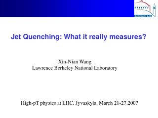
Measured current decay after a quench Dipole GSI001 measured at Brookhaven National Laboratory JUAS February 2012
Calculating temperature rise from the current decay curve U(q) (calculated) J 2 dt (measured) JUAS February 2012
Calculated temperature • calculate the U(q) function from known materials properties • measure the current decay profile • calculate the maximum temperature rise at the point where quench starts • we now know if the temperature rise is acceptable - but only after it has happened! • need to calculate current decay curve before quenching JUAS February 2012
Growth of the resistive zone the quench starts at a point and then grows in three dimensions via the combined effects of Joule heating and thermal conduction * JUAS February 2012
Quench propagation velocity 1 • resistive zone starts at a point and spreads outwards • the force driving it forward is the heat generation in the resistive zone, together with heat conduction along the wire • write the heat conduction equations with resistive power generation J2r per unit volume in left hand region and r = 0 in right hand region. resistive v qt temperature superconducting qo xt distance where: k = thermal conductivity, A = area occupied by a single turn,g = density,C = specific heat,h = heat transfer coefficient,P = cooled perimeter, r= resistivity, qo = base temperature Note: all parameters are averaged over A the cross section occupied by one turn assume xt moves to the right at velocity v and take a new coordinatee = x-xt= x-vt JUAS February 2012
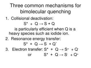
Quench propagation velocity 2 Jc rCu Jop reff qc qo qs qc qo qs qt when h = 0, the solution for q which gives a continuous join between left and right sides at qt gives the adiabatic propagation velocity recap Wiedemann Franz Law r(q).k(q) = Loq • what to say about qt ? • in a single superconductor it is just qc • but in a practical filamentary composite wire the current transfers progressively to the copper • current sharing temperature qs = qo + margin • zero current in copper below qs all current in copper above qc • take a mean transition temperature qt = (qs + qc )/2 JUAS February 2012
Quench propagation velocity 3 av av v the resistive zone also propagates sideways through the inter-turn insulation (much more slowly) calculation is similar and the velocity ratio a is: Typical values a = 0.01 - 0.03 vad = 5 - 20 ms-1 so the resistive zone advances in the form of an ellipsoid, with its long dimension along the wire Some corrections for a better approximation • because C varies so strongly with temperature, it is better to calculate an averaged C from the enthalpy change • heat diffuses slowly into the insulation, so its heat capacity should be excluded from the averaged heat capacity when calculating longitudinal velocity - but not transverse velocity • if the winding is porous to liquid helium (usual in accelerator magnets) need to include a time dependent heat transfer term • can approximate all the above, but for a really good answer must solve (numerically) the three dimensional heat diffusion equation or, even better, measure it! JUAS February 2012
Resistance growth and current decay - numerical vdt vdt avdt avdt * in time dt zone 1 grows v.dt longitudinally and a.v.dt transversely temperature of zone grows by dq1 =J2 r(q1)dt / g C(q1) resistivity of zone 1 isr(q1) calculate resistance and hence current decay dI = R / L.dt in time dt add zone n: v.dt longitudinal and a.v.dt transverse temperature of each zone grows by dq1 =J2r(q1)dt/gC(q1) dq2 =J2r(q2)dt/gC(q2) dqn=J2r(q1)dt /gC(qn) resistivity of each zone isr(q1) r(q2) r(qn) resistance r1= r(q1) * fg1(geom factor) r2= r(q2) * fg2rn= r(qn) * fgn calculate total resistance R = r1+ r2 +rn..and hence current decay dI = (IR/L)dt when I 0 stop start resistive zone 1 JUAS February 2012
Quench starts in the pole region * * * * * * the geometry factor fg depends on where the quench starts in relation to the coil boundaries JUAS February 2012
Quench starts in the mid plane * * * JUAS February 2012
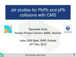
Computer simulation of quench (dipole GSI001) pole block 2nd block mid block JUAS February 2012
OPERA: a more accurate approach solve the non-linear heat diffusion & power dissipation equations for the whole magnet JUAS February 2012
Compare with measurement • can include • ac losses • flux flow resistance • cooling • contact between coil sections but it does need a lot of computing Coupled transient thermal and electromagnetic finite element simulation of Quench in superconducting magnets C Aird et al Proc ICAP 2006 available at www.jacow.org JUAS February 2012
Methods of quench protection:1) external dump resistor • detect the quench electronically • open an external circuit breaker • force the current to decay with a time constant where • calculate qmax from Note: circuit breaker must be able to open at full current against a voltage V = I.Rp (expensive) JUAS February 2012
Methods of quench protection:2) quench back heater • detect the quench electronically • power a heater in good thermal contact with the winding • this quenches other regions of the magnet, effectively forcing the normal zone to grow more rapidly higher resistance shorter decay time lower temperature rise at the hot spot Note: usually pulse the heater by a capacitor, the high voltages involved raise a conflict between:- - good themal contact - good electrical insulation method most commonly used in accelerator magnets JUAS February 2012
Methods of quench protection:3) quench detection (a) I internal voltage after quench V • not much happens in the early stages - small dI/dt small V • but important to act soon if we are to reduce TQ significantly • so must detect small voltage • superconducting magnets have large inductance large voltages during charging • detector must reject V = LdI/dt and pick up V = IR • detector must also withstand high voltage -as must the insulation t JUAS February 2012
Methods of quench protection:3) quench detection (b) D i) Mutual inductance • ii) Balanced potentiometer • adjust for balance when not quenched • unbalance of resistive zone seen as voltage across detector D • if you worry about symmetrical quenches connect a second detector at a different point detector subtracts voltages to give • adjust detector to effectively make L = M • M can be a toroid linking the current supply bus, but must be linear - no iron! JUAS February 2012
Methods of quench protection:4) Subdivision • resistor chain across magnet - cold in cryostat • current from rest of magnet can by-pass the resistive section • effective inductance of the quenched section is reduced reduced decay time • reduced temperature rise • current in rest of magnet increased by mutual inductance effects • quench initiation in other regions • often use cold diodes to avoid shunting magnet when charging it • diodes only conduct (forwards) when voltage rises to quench levels • connect diodes 'back to back' so they can conduct (above threshold) in either direction JUAS February 2012
Quenching: concluding remarks always do quench calculations before testing magnet • magnets store large amounts of energy - during a quench this energy gets dumped in the winding intense heating (J ~ fuse blowing) possible death of magnet • temperature rise and internal voltage can be calculated from the current decay time • computer modelling of the quench process gives an estimate of decay time – but must decide where the quench starts • if temperature rise is too much, must use a protection scheme • active quench protection schemes use quench heaters or an external circuit breaker - need a quench detection circuit which rejects LdI/dt and is 100% reliable • passive quench protection schemes are less effective because V grows so slowly at first - but are 100% reliable JUAS February 2012
Cryogenics: the working fluids the gap JUAS February 2012
the most basic refrigerator uses compressor power to extract heat from low temperature and reject a larger quantity of heat at room temperature Carnot says the Coefficient of Performance CoP = cooling power / input power Refrigeration 15 10 5 CoP qh = 320K at 4.2K CoP = 1.3% JUAS February 2012
Collins helium liquefier gas from compressor heat exchanger - cooled by upstreaming gas heat exchanger - cooled by upstreaming gas expansion turbine - cooled by doing work repeat expansion valve - cooled by Joule Thompson effect gas liquid from Helium Cryogenics SW Van Sciver pub Plenum 1986 JUAS February 2012
Practical refrigeration efficiencies recap Carnot • practical efficiencies as a fraction of Carnot, plotted for operating refrigerators, as a function of cooling power. • operating temperature does not make much difference • but size matters! TR Strowbridge: 'Cryogenic refrigerators, an updated survey' NBS TN655 (1974) JUAS February 2012
helium has the lowest boiling point of all gases and is therefore used for cooling superconducting magnets below thelamda pointa second liquid phase is formed, known as Helium 2 or superfluid it has zero viscosity and a very high thermal conductivity Some numbers for helium boiling point at 1 atmos 4.22K lamda point at 0.0497 atmos 2.17K density of liquid at 4.22K 0.125 gm/cc density of gas at 4.22K 0.0169gm/cc density of gas at NTP 1.66x10⁻⁴gm/cc latent heat of vaporization 20.8J/gm enthalpy change 4.2K293K 1506J/gm ratio Denthalpy/latent heat 72 Properties of Helium JUAS February 2012
Subcooled Helium II He 1 He 2 pump out gas at 0.016atm • HeII is an excellent coolant because of its high thermal conductivity and specific heat • NbTi works much better at the lower temperature • but for practical engineering, it is inconvenient operate at pressures below atmospheric • the 'lamda plate' allows us to produce HeII in a system operating at atmospheric pressure • used in LHC and commercial NMR magnets 1 atm gas 4.2K 1 atm liquid 1.8K JUAS February 2012
Accelerator magnet cryostat essentials current supply leads high vacuum radiation shield liquid helium beam tube magnet feeds to next magnet mechanical supports JUAS February 2012
1) Gas conduction at low pressures (<10Pa or 10-4 torr), that is when the mean free path ~ 1m > distance between hot and cold surfaces Cryogenic heat leaks where hg depends on the accommodation coefficient; typical values for helium not usually a significant problem, check that pressure is low enough and use a sorb 2) Solid conduction look up tables of conductivity integrals a more convenient form is 3) Radiation transfer between two surfaces heat flux Stefan Boltzmann constant s = 5.67x10⁻⁸ Wm-2K-4 4) Current Leadsoptimization problem; trade off Ohmic heating against conducted heat - lecture 5 5) Other sourcesac losses, resistive joints, particle heating etc JUAS February 2012
pure metals have much higher k than alloys annealing increases k for pure metals can get a reasonable estimate from Weidemann Franz Law Thermal conductivity thermal conductivity Wm-1K-1 where the Lorentz number Lo = 2.45 x 10⁻⁸ WW K-2 temperature K JUAS February 2012
recapitulate Thermal conductivity integrals where Q` is heat flow A is area of cross section and L is length read the difference between qc and qh from the graph thermal conductivity integral Wm-1K-1 selected values temperature K JUAS February 2012
Radiation and emissivities 1.0 Oxidized metals anodized aluminium Oxidized metals anodized aluminium effective emissivity As received metals including stainless steel, aluminium and copper As received metals including stainless steel, aluminium and copper 0.1 Mechanically & chemically polished stainless, Al, Cu Mechanically & chemically polished stainless, Al, Cu Aluminized Mylar Silver plated metals & aluminized Mylar 0.01 77K to 4.2K 300K to 77K often work in terms of an effective emissivitiy between two temperatures er Stefan Boltzmann constant s = 5.67x10⁻⁸ Wm-2K-4 JUAS February 2012
Because radiated power goes as q4 you can reduce it by subdividing the gap between hot and cold surface using alternating layers of shiny metal foil or aluminized Mylar and insulating mesh. Note - the structure must be open for pumping. - care needed in making corners of superinsulation - aluminized Mylar is only useful above ~80K, low temperature radiation passes through the aluminium coating The greatest radiation heat leak is from room temperature to the radiation shield. For this reason, superinsulation is most often used on the radiation shield Superinsulation hot surface shiny metal insulating mesh cold surface Some typical values of effective emissivity er for superinsulation * Jehier SA BP 29-49120 Chemille France JUAS February 2012
Cryogenics: concluding remarks • producing and maintaining low temperatures depends on liquefied gases - helium for the lowest temperature • refrigeration depends on alternately compressing and expanding the gas - heat exchange can extend the temperature reach • lots of power needed to produce low temperature cooling ~ 1000× for liquid helium • for an efficient cryostat must minimize heat inleak - conduction, convection and radiation JUAS February 2012