Download
1 / 43
430 likes | 851 Vues
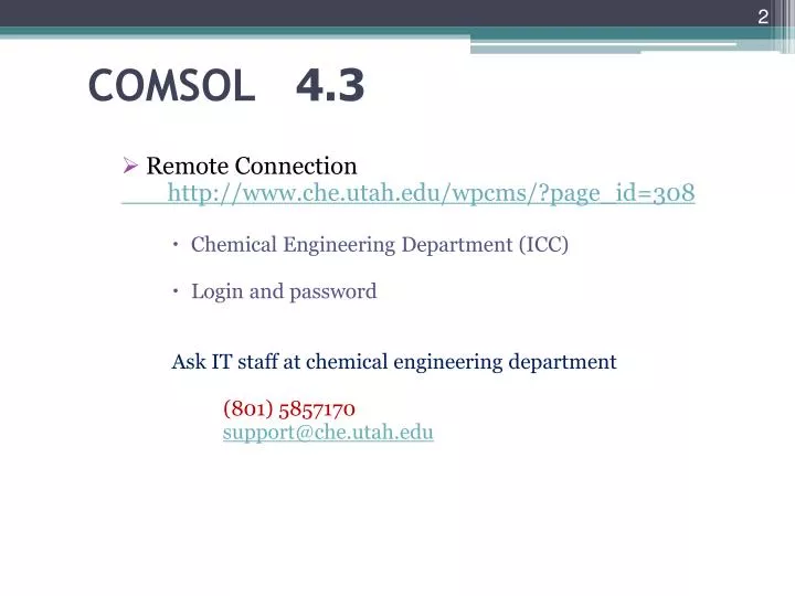
COMSOL 4.3. Remote Connection http://www.che.utah.edu/wpcms/?page_id=308 Chemical Engineering Department (ICC) Login and password Ask IT staff at chemical engineering department (801) 5857170 support@che.utah.edu. terminal-1.chemeng.utah.edu terminal-2.chemeng.utah.edu

E N D
COMSOL4.3 • Remote Connection http://www.che.utah.edu/wpcms/?page_id=308 • Chemical Engineering Department (ICC) • Login and password Ask IT staff at chemical engineering department (801) 5857170 support@che.utah.edu
terminal-1.chemeng.utah.edu terminal-2.chemeng.utah.edu terminal-3.chemeng.utah.edu terminal-4.chemeng.utah.edu terminal-5.chemeng.utah.edu terminal-6.chemeng.utah.edu terminal-7.chemeng.utah.edu terminal-8.chemeng.utah.edu terminal-9.chemeng.utah.edu terminal-10.chemeng.utah.edu terminal-11.chemeng.utah.edu terminal-12.chemeng.utah.edu terminal-13.chemeng.utah.edu terminal-14.chemeng.utah.edu terminal-15.chemeng.utah.edu terminal-16.chemeng.utah.edu terminal-17.chemeng.utah.edu terminal-18.chemeng.utah.edu terminal-19.chemeng.utah.edu terminal-20.chemeng.utah.edu COMSOL -Remote Connection • Windows user To launch remote desktop START--> RUN--> type "mstsc.exe" “Or in Vista” Start --> All Programs --> Accessories --> Remote Desktop Connection Use your ICC login and password. You will be connected remotely to ICC machines • Mac or Linux user Search for the software you need on line
COMSOL-4.3 www.comsol.com • Background and applications of COMSOL • Free Webinar: http://www.comsol.com/events/webinars/ • Free tutorial CDs • Updated information
COMSOL Application You can use COMSOL Multiphysics in many application areas, just a few examples being: • Chemical reactions • Diffusion • Fluid dynamics • Fuel cells and electrochemistry • Bioscience • Acoustics • Electromagnetics • Geophysics
COMSOL Application • Heat transfer • Microelectromechanical systems (MEMS) • Microwave engineering • Optics • Photonics • Porous media flow • Quantum mechanics • Radio-frequency components • Semiconductor devices • Structural mechanics • Transport phenomena • Wave propagation
The COMSOL Modules • AC/DC Module • Acoustics Module • Chemical Engineering Module • Electrochemistry • Fluid flow • Heat transfer • Plasma • Radio frequency • Structural mechanics • Mathematics The optional modules are optimized for specific application areas. They offer discipline standard terminology and interfaces, materials libraries, specialized solvers, elements, and visualizationtools.
The Chemical Engineering Module The Chemical Engineering Module presents a powerful way of modeling equipment and processes in chemical engineering. It provides customized interfaces and formulations for momentum, mass, and heat transport coupled with chemicalreactions for applications such as: • Reaction engineering and design • Heterogeneous catalysis • Separation processes • Fuel cells and industrial electrolysis • Process control together with Simulink
The Chemical Engineering Module … COMSOL Multiphysics excels in solving systems of couplednonlinear PDEs that can include: • Heat transfer • Mass transfer through diffusion and convection • Fluid dynamics • Chemical reaction kinetics • Varying material properties The multiphysics capabilities of COMSOL can fully couple and simultaneously model fluid flow, mass and heat transport, and chemical reactions.
The Chemical Engineering Module … In fluid dynamics you can model fluid flow through porous media or characterize flow with the Navier-Stokes equations. It is easy to represent chemical reactions by source or sink terms in mass and heat balances. All formulations exist for both Cartesian and Cylindrical coordinates (for axisymmetric models) as well as for stationary and time-dependent cases.
The Chemical Engineering Module … The available application modes are: • Momentum balances • Incompressible Navier-Stokes equations • Darcy’s law • Brinkman equations • Non-Newtonian flow • Nonisothermal and weakly compressible flow • Turbulent flow, k-ε turbulence model • Turbulent flow, k-ω turbulence model • Multiphase flow
The Chemical Engineering Module … • Energy balances • Heat conduction • Heat convection and conduction • Mass balances • Diffusion • Convection and diffusion • Electrokinetic flow • Maxwell-Stefan diffusion and convection • Nernst-Planck transport equations
The Modeling Process The modeling process in COMSOL consists of six main steps: • Selecting the appropriate application mode in the Model Navigator. • Drawing or importing the model geometry in the Draw Mode. • Setting up the subdomain equations and boundary conditions in the Physics Mode. • Meshing in the Mesh Mode. • Solving in the Solve Mode. • Postprocessing in the Postprocessing Mode.
1. The Model Navigator When starting COMSOL Multiphysics, you are greeted by the Model Navigator. Here you begin the modeling process and control all program settings. It lets you select space dimension and application modes to begin working on a new model, open an existing model you have already created, or open an entry in the Model Library. COMSOL Multiphysics provides an integrated graphical user interface where you can build and solve models by using predefined physics modes
2. Creating Geometry An important part of the modeling process is creating the geometry. The COMSOL Multiphysics user interface contains a set of CAD tools for geometry modeling in 1D, 2D, and 3D. The CAD Import Module provides an interface for import of Parasolid, SAT (ACIS), STEP, and IGES formats. In combination with the programming tools, you can even use images and magnetic resonance imaging (MRI) data to create a geometry.
Axes and Grid In the COMSOL Multiphysics user interface you can set limits for the model axes and adjust the grid lines. The grid and axis settings help you get just the right view to produce a model geometry. To change these settings, use the Axes/Grid Settings dialog box that you open from the Options menu. You can also set the axis limits with the zoom functions.
Axes and Grid The default names for coordinate systems vary with the space dimension: • Models that you open using the space dimensions 1D, 2D, and 3D use the Cartesian coordinates x, y, and z. • In 1D axisymmetric geometries the default coordinate is r, the radial direction. The x-axis represents r. • In 2D axisymmetric geometries the x-axis represents r, the radial direction, and the y-axis represents z, the height coordinate.
3. Modeling Physics and Equations From the Physics menu you can specify all the physics and equations that define a model including: • Boundary and interface conditions • Domain equations • Material properties • Initial conditions
4. Creating Mesh When the geometry is complete and the parameters are defined, COMSOL Multiphysics automatically meshes the geometry. However, you can take charge of the mesh-generation process through a set of control parameters. For a 2D geometry the mesh generator partitions the subdomains into triangular or quadrilateral mesh elements. Similarly, in 3D the mesh generator partitions the subdomains into tetrahedral, hexahedral, or prism mesh elements.
5. Solution Next comes the solution stage. Here COMSOL Multiphysics comes with a suite of solvers for stationary, eigenvalue, and time-dependent problems. For solving linear systems, the software features both direct and iterative solvers. A range of preconditioners are available for the iterative solvers. COMSOL sets up solver defaults appropriate for the chosen application mode and automatically detects linearity and symmetry in the model. A segregatedsolver provides efficient solution schemes for large multiphysics models, turbulence modeling, and other challenging applications.
6. Postprocessing For postprocessing, COMSOL provides tools for plotting and postprocessing any model quantity or parameter: • Surface plots • Slice plots • Isosurfaces • Contour plots • Arrow plots • Streamline plots and particle tracing • Cross-sectional plots • Animations • Data display and interpolation • Integration on boundaries and subdomains
Report Generator To document your models, the COMSOL Report Generator provides a comprehensive report of the entire model, including graphics of the geometry, mesh, and postprocessing quantities. You can print the report directly or save it as an HTML file for viewing through a web browser and further editing.
COMSOL -Example Flow Past the Cylinder Getting Started ComsolMultiphysics4.2 • Must be known • Properties of the fluid/material • Objective of the problem
Example: Flow Past a Cylinder- Benchmark test for CFD algorithms Unsteady, incompressible flow Wake formation- Unordered eddies Large drag on body Cylinder: Off center, otherwise steady state symmetric flow Objective : Frequency and amplitude of vibration (Forces) at various fluid speed Reynolds # based on cylinder diameter Slow flow (below Re # 100) -steady flow (start with this to correct simple errors and mistakes) Fast flow - (Re # = 100)- developed Von Karman vortex street (not fully turbulence) (time dependent simulation)
Circle 1 1 In the Model Builder window, right-click Geometry 1 and choose Circle. 2 Go to the Settings window for Circle. 3 Locate the Position section. In the x edit field, type 0.2. 4 In the y edit field, type 0.2. 5 Locate the Size and Shape section. In the Radius edit field, type 0.05. Rectangle 1 1 In the Model Builder window, right-click Model 1>Geometry 1 and choose Rectangle. 2 Go to the Settings window for Rectangle. 3 Locate the Size section. In the Width edit field, type 2.2. 4 In the Height edit field, type 0.4.
Difference 1 1 Right-click Geometry 1 and choose Difference. 2 Go to the Settings window for Difference. 3 Locate the Difference section. Under Objects to add, click Activate Selection. 4 Select the object r1 only. 5 Under Objects to subtract, click Activate Selection. 6 Select the object c1 only. 7 In the Model Builder window, right-click Geometry 1 and choose Build All.
M A T E R I A L S Material 1 1 In the Model Builder window, right-click Model 1>Materials and choose Material. 2 Go to the Settings window for Material. 3 Locate the Material Contents section. In the Material contents table, enter the
Inlet 1 1 In the Model Builder window, right-click Model 1>Laminar Flow and choose Inlet. 2 Select Boundary 1 only. 3 Go to the Settings window for Inlet. 4 Locate the Velocity section. In the U0 edit field, type U_mean*6*s*(1-s)*step1(t[1/s]). Outlet 1 1 In the Model Builder window, right-click Laminar Flow and choose Outlet. 2 Select Boundary 4 only.
M E S H : 1 In the Model Builder window, click Model 1>Mesh 1. 2 Go to the Settings window for Mesh. 3 Locate the Mesh Settings section. From the Element size list, select Finer. 4 Click the Build All button.
Step 1: Time Dependent 1 In the Model Builder window, expand the Study 1 node, then click Step 1: Time Dependent. 2 Go to the Settings window for Time Dependent. 3 Locate the Study Settings section. In the Times edit field, type range(0,0.2,3.4) range(3.5,0.02,7). In the Model Builder window, right-click Study 1 and choose Show Default Solver. 5 Expand the Study 1>Solver Configurations node
Solver 1 1 In the Model Builder window, expand the Study 1>Solver Configurations>Solver 1 node, then click Time-Dependent Solver 1. 2 Go to the Settings window for Time-Dependent Solver. 3 Click to expand the Time Stepping section. 4 From the Steps taken by solver list, select Intermediate. 5 In the Model Builder window, right-click Study 1 and choose Compute.
Solver Karman path Fully developed flow