Download
1 / 29
290 likes | 421 Vues
ISCAS 2005. Performance Model for Inter-chip Busses Considering Bandwidth and Cost. Authors: Brock J. LaMeres University of Colorado, Boulder, CO Sunil P. Khatri Texas A&M University, College Station, TX. Problem : Packaging Limits Performance. IC

E N D
ISCAS 2005 Performance Model for Inter-chip Busses Considering Bandwidth and Cost Authors: Brock J. LaMeres University of Colorado, Boulder, CO Sunil P. Khatri Texas A&M University, College Station, TX. “Performance Model for Inter-chip Busses”
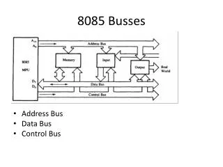
Problem : Packaging Limits Performance IC “Moore’s Law” - # of transistors will double every 18 months Package “Rent’s Rule” - # of I/O will double in next 10 years Transistor Technology is Faster than Package Technology “Performance Model for Inter-chip Busses”
Outline Inductive noise in packaging Package performance model Relationship with inductive parasitics “Bandwidth per unit cost” metric Experimental results Model versus SPICE Conclusions “Performance Model for Inter-chip Busses”
Inductive Noise in Packaging L11 = Inductance of pwr/gnd pin that current is being switched through. 1) Supply Bounce Switching current through inductive packaging induces voltage: Multiple Signals Switching Increase the Problem: n = # of drivers sharing the power/gnd pin (L11). “Performance Model for Inter-chip Busses”
Inductive Noise in Packaging M1k = Mutual Inductance between pwr/gnd pin and kth signal pin. 2) Pin-to-Pin Coupling Switching Signals Couple Voltage onto Neighbors: Multiple Signals Switching Increase the Problem: “Performance Model for Inter-chip Busses”
Analytical Model S S G S S P S S G S S P S S G S S P WBUS WBUS : # of signals in the bus Bus Parameters S S G S S P S S G S S P S S G S S P NG : # of Grounds in the bus “Performance Model for Inter-chip Busses”
Analytical Model P S S G S S P S S G S S P S S G S S Repetitive Pattern of Signal, Power, and Ground Pins Bus Parameters SPG : (# of Signals) : (# of PWR’s) : (# of GND’s) = 4:1:1 in above example “Performance Model for Inter-chip Busses”
Analytical Model Slewrate v(t) dv Bus Performance Description dt t “Performance Model for Inter-chip Busses”
Analytical Model Risetime 90% v(t) (0.8)VDD VDD Bus Performance Description 10% t “Performance Model for Inter-chip Busses”
Analytical Model Minimum Unit Interval Bus Performance Description DATA DATA DATA UI “Performance Model for Inter-chip Busses”
DATA DATA DATA DATA DATA DATA DATA DATA DATA Analytical Model Bus Throughput Tx Rx Bus Performance Description WBUS “Performance Model for Inter-chip Busses”
Analytical Model Maximum Acceptable Ground Bounce pVDD v(t) VDD Bus Performance Limits NOISE t (ptypical = 5%) “Performance Model for Inter-chip Busses”
Analytical Model Maximum Ground Bounce Model Development Self Contribution Coupling Contribution “Performance Model for Inter-chip Busses”
Analytical Model Maximum Slewrate Model Development - pull out (di/dt) - convert to (dv/dt) “Performance Model for Inter-chip Busses”
Analytical Model Minimum Risetime :But since Model Development - convert slewrate to risetime “Performance Model for Inter-chip Busses”
Analytical Model Maximum Datarate :Also, since Model Development - convert Risetime to Datarate Maximum Throughput :Finally, we have “Performance Model for Inter-chip Busses”
Experimental Results QFP – Wire Bond BGA – Wire Bond BGA – Flip-Chip Per-pin and Bus throughput values computed for 3 packages Compared our model with SPICE simulations “Performance Model for Inter-chip Busses”
Experimental Results Per-Pin Data-Rate Bus Throughput QFP Wire-Bond Package Simulations ModelSimulation - Throughput reaches an asymptotic limit as channels are added “Performance Model for Inter-chip Busses”
Experimental Results Per-Pin Data-Rate Bus Throughput BGA Wire-Bond Package Simulations - Level 1 : BGA Increases Performance Over QFP “Performance Model for Inter-chip Busses”
Experimental Results Per-Pin Data-Rate Bus Throughput BGA Flip-Chip Package Simulations - Level 2: Flip-Chip Increases Performance Over Wire-Bond “Performance Model for Inter-chip Busses”
Experimental Results Units = (Mb/$) Cost Must Also Be Considered in Analysis Bandwidth Per Cost This Metric Represents “Cost Effectiveness of the Bus” “Performance Model for Inter-chip Busses”
Experimental Results Bandwidth Per Cost Results Faster Narrower Busses = More Cost Effective “Performance Model for Inter-chip Busses”
Conclusions Presented a model for bus performance Accounts for inductive parasitics in packaging Developed a “bandwidth-per-unit-cost” metric to evaluate packages Experiments indicate Strong agreement with SPICE simulation Throughput for a bus reaches asymptotic limit as channels added Increase in channels compensated by decrease in per-pin throughput Optimal number of channels is small (4-8) “Bandwidth-per-unit-cost” experiments indicate Flip-chip packages are actually most cost-effective Narrower buses have better bandwidth-per-unit-cost “Performance Model for Inter-chip Busses”
Thank you! “Performance Model for Inter-chip Busses”
Backup Slides “Performance Model for Inter-chip Busses”
Example PACKAGE - Rent’s Rule On-Chip - 8 bit Data Bus - 300 Mb/s Package- Need (8)(300M) = 2400 Mb/s IC Core - Moore’s Law “Performance Model for Inter-chip Busses”
Example 2400 Mb/s X X X Need: X • QFP – Wire Bond BGA – Wire Bond BGA – Flip-Chip • 4 bits wide, SPG=2:1:1 - 1 bit wide, SPG=2:1:1 - 1 bit wide, SPG=2:1:1 - 16 bits wide, SPG=4:1:1 - 1 bit wide, SPG=4:1:1 - 1 bit wide, SPG=8:1:1 “Performance Model for Inter-chip Busses”
Example Most Cost Effective: - BGA-WB- Wbus = 1- SPG = 2:1:1 Cost of Each Bus Configuration “Performance Model for Inter-chip Busses”
Experimental Results $ Cost per Bus Configuration Performance Increases with Cost (Package, SPG) “Performance Model for Inter-chip Busses”