Download
1 / 26
260 likes | 264 Vues
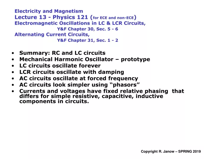
Electricity and Magnetism Lecture 13 - Physics 121 ( for ECE and non-ECE ) Electromagnetic Oscillations in LC & LCR Circuits, Y&F Chapter 30, Sec. 5 - 6 Alternating Current Circuits, Y&F Chapter 31, Sec. 1 - 2. Summary: RC and LC circuits Mechanical Harmonic Oscillator – prototype

E N D
Electricity and MagnetismLecture 13 - Physics 121 (for ECE and non-ECE)Electromagnetic Oscillations in LC & LCR Circuits, Y&F Chapter 30, Sec. 5 - 6Alternating Current Circuits, Y&F Chapter 31, Sec. 1 - 2 • Summary: RC and LC circuits • Mechanical Harmonic Oscillator – prototype • LC circuits oscillate forever • LCR circuits oscillate with damping • AC circuits oscillate at forced frequency • AC circuits look simpler using “phasors” • Currents and voltages have fixed relative phasing that differs for simple resistive, capacitive, inductive components in circuits.
R R E E C L Voltage across C related to Q - integral of current. Voltage will LAG current Voltage across L related to derivative of current. Voltage will LEAD current Growth Phase Decay Phase Now: LCR in same circuit + periodic EMF –> New effects R • Resonant oscillations in LC circuit – ignore damping L • Damped oscillation in LCR circuit - not driven • Circuit driven by external AC frequency wD=2pf • which could be the ‘resonant’ frequency. C • New descriptive quantities: • Generalized resistances: reactances, impedance R L C Time dependent effects - RC and RL circuits with constant EMF
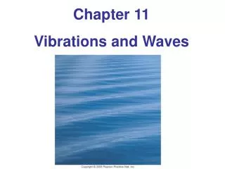
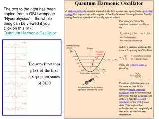
Definition: oscillating system • State ( t ) = state( t + T ) = ……. = state( t + NT ). • T is the “period” -Time to complete one complete cycle • f = 1/T is the frequency. w = 2pf is the “angular frequency” • “State” can mean: position and velocity, electric & magnetic fields,… Mechanical Example: Simple harmonic oscillator (undamped) Mechanical energy is conserved` no friction Systems that oscillate obey equations like this... With solutions like this... What oscillates? position & velocity, acceleration, spring force, Energy oscillates between 100% kinetic and 100% potential: Kmax = Umax Model: Resonant mechanical oscillations (SHM)
a + b Kirchhoff loop equation: L E C Substitute: An oscillator equation results solution: derivative: What oscillates? Charge, current, B & E fields, UB, UE Peaks of current and charge are out of phase by 900 Electrical Oscillations in an LC circuit, zero resistance Charge capacitor fully to Q0=CEthen switch to “b” Note: could have chosen sin rather than cos, with phase constant f adjusted
Total electrical potential energy is constant: The peak values UE0 and UB0 are equal: Electrical Oscillations in an LC circuit, zero resistance
The definition and imply that: oscillator equation • Either (no current ever flows) OR: • Oscillator solution: • To evaluate w0: plug the first and second derivatives of the solution into the differential equation. • The resonant oscillation frequency w0 is: Details: Derive Oscillator Equation from Energy Conservation • The total energy: • It is constant so:
Oscillations Forever? 13 – 1: What do you think will happen to the oscillations in an ideal LC circuit (versus a real circuit) over a long time? • They will stop after one complete cycle. • They will continue forever. • They will continue for awhile, and then suddenly stop. • They will continue for awhile, but eventually die away. • There is not enough information to tell what will happen.
Potential Energy alternates between all electrostatic and all magnetic – two reversals per period t • C is fully charged twice • each cycle (opposite polarity) • So is L • Peaks are 90o out of phase
C L a) Find the oscillation period and frequency f = ω / 2π b) Find the maximum (peak) current (differentiate Q(t) ) c) When does current i(t) have its first maximum? When |sin(w0t)| = 1 First One at: Maxima of Q(t): All energy is in E field Maxima of i(t): All energy is in B field Maxima of current at T/4, 3T/4, … (2n+1)T/4 Others at: A 4 µF capacitor is charged to E = 5.0 V, and then connected to a 0.3 Henry inductance in an LC circuit Example: Use preceding solutions with f = 0
Find the expression for the current in the circuit: c) How long until the capacitor charge is exactly reversed? That occurs every ½ period, given by: Example • Find the voltage across the capacitor in the circuit as a function of time. L = 30 mH, C = 100 mF.The capacitor has charge Q0 = 0.001 C. at time t = 0. The resonant frequency is: The voltage across the capacitor has the same time dependence as the charge: At time t = 0, Q = Q0, so chose phase angle f = 0 to match initial condition.
Which Current is Greatest? 13 – 2: The expressions below could represent the charge on a capacitor in an LC circuit as a function of time. Which one has the greatest peak current magnitude? • Q(t) = 2 sin(5t) • Q(t) = 2 cos(4t) • Q(t) = 2 cos(4t+p/2) • Q(t) = 2 sin(2t) • Q(t) = 4 cos(2t)
I. II. III. LC circuit oscillation frequencies 13 – 3: The three LC circuits below have identical inductors and capacitors. Order the circuits according to their oscillation frequency in ascending order. • I, II, III. • II, I, III. • III, I, II. • III, II, I. • II, III, I.
a R + b E C The resistor dissipates stored energy. The power is: L Modified oscillator equation has damping (decay) term: Find transient solution: oscillations with exponential decay (under- damped case) Shifted resonant frequency w’ can be real or imaginary “damped frequency” Underdamped: Overdamped Critically damped Q(t) LCR Series Circuit adds series resistance: Shifted Oscillations but with Damping Charge capacitor fully to Q0=CEthen switch to “b”
Resonant frequency with damping 13 – 4: How does the resonant frequency w0 for an ideal LC circuit (no resistance) compare with w’ for an under-damped LCR circuit whose resistance is not negligible? • The resonant frequency for the damped circuit is higher than for the ideal one (w’ > w0). • The resonant frequency for the damped circuit is lower than for the ideal one (w’ < w0). • The resistance in the circuit does not affect the resonant frequency—they are the same (w’ = w0). • The damped circuit has an imaginary value of w’.
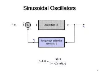
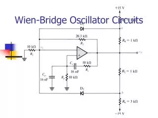
Apply external voltage Real, instantaneous current flows • Sinusoidal EMF appears in rotating coils in a magnetic field (Faraday’s Law) • Slip rings and brushes take EMF from the coil and produce sinusoidal AC voltage and current. • External circuits are driven by sinusoidal EMF • Current in external circuit may lead or lag EMF according to character of the load connected. Alternating External Voltage (AC) Source • Commercial electric power (home or office) is AC, with frequency = 60 Hz in U.S, 50 Hz in most other countries. • High transmission voltage Lower i2R loss than DC, and is reduced for distribution to customers by using transformers. • “Steady State” sinusoidal signal has frequency wD: • “Phase angle” F is between current and EMF in the driven circuit. • You might (wrongly) expect F = 0 • F is positive when Emax leads Imax and negative otherwise (convention)
load the driving frequency STEADY STATE RESPONSE (after transients die away): . Current in load is sinusoidal, has same frequency as source ... but . Current may be retarded or advanced relative to E by “phase angle” F for the whole circuit(due to inertia L and stiffness 1/C). resonant frequency peak applied voltage DEFINE: IMPEDANCE IS THE RATIO OF PEAK (or RMS) EMF TO PEAK (or RMS) CURRENT. peak current • Impedance for a circuit is a function of resistances, reactances, and how they are interconnected Apply Sinusoidal AC Source to circuit KIRCHHOFF RULES APPLY: . In a series branch, current has the same amplitude and phase everywhere. . Across parallel branches, voltage drops have the same amplitudes and phases . At nodes (junctions), instantaneous net currents in & out are conserved
Peak amplitudes lengths of the phasors. • Measurable, real, instantaneous values of i( t ) and • E( t ) are projections of the phasors onto the x-axis. F “phase angle”: the angle from current phasor to EMF phasor in the driven circuit. wDt and are independent Real X • Current is the same (phase included) everywhere • in a single essential branch of any circuit. • Current vector is reference for series LCR circuit. • Applied EMF Emax(t) leads or lags the current by a • phase angle F in the range [-p/2, +p/2] Relative phases for individual series circuit elements (to be shown): • Voltage across R is in phase with the current. • Voltage across C lags the current by 900. • Voltage across L leads the current by 900. VR VC VL XC>XL XL>XC represent currents and potentials as vectors rotating at frequency wD in complex plane Phasors Imaginary Y
Peak voltage and current amplitudes are just the coefficients out front • represented by lengths of rotating phasors • Simplistic time averaging of periodic quantities gives zero (and useless) results). • example: integrate over a whole number of periods – one t is enough (wt=2p) Integrand is odd over a full cycle The meaningful types of quantities in AC circuits can be instantaneous, peak, or average (RMS) • Instantaneous voltages and currents refer to a specific time: • oscillatory, depend on time through argument “wt” • possibly advanced or retarded relative to each other by phase angle • represented by x-component of rotating “phasors” – see slides below So how should “average” be defined?
“RMS averages” are used the way instantaneous quantities were in DC circuits: • “RMS” means “root, mean, squared”. NOTE: • “Rectified average values” are useful for DC but seldom used in AC circuits: • Integrate |cos(wt)| over one full cycle or cos(wt) over a positive half cycle Integrand on a whole cycle is positive after squaring Prescription: RMS Value = Peak value / Sqrt(2) Definitions of Average AC Quantities
Current/Voltage Phases in Resistors, Capacitors, and Inductors VR& Im in phase Resistance VC lags Im by p/2 Capacitive Reactance VL leads Im by p/2 Inductive Reactance Same Phase currrent • Sinusoidal current i(t) = Imcos(wDt). Peak is Im • vR(t) ~ i(t) vL(t) ~ derivative of i(t) Vc(t) ~ integral of i(t) • Peak voltages across R, L, or C lead/lag current by 0, p/2, -p/2 radians • Ratios of peak voltages to peak currents are called “reactances” in C’s and L’s • Phases of voltages in a series branch are relative tothe current phasor.
i(t) vR( t ) Applied EMF: From Kirchhoff loop rule: Time dependent current: The phases of vR(t) and i(t) coincide The ratio of the AMPLITUDES (peaks) VRto Im is the resistance: Peak current and peak voltage are in phase across a resistance, rotating at the driving frequency wD AC current i(t) and voltage vR(t) in a resistor are in phase Extra Discussion From voltage drop across R:
i(t) Applied EMF: L vL(t) From Kirchhoff loop rule: Time dependent current: Note: Definition: inductive reactance Voltage phasor across an inductor leads current by +p/2 (F positive) • Inductive Reactance • limiting cases • w 0: Zero reactance. • Inductor acts like a wire. • w infinity: Infinite reactance. • Inductor acts like a broken wire. The RATIO of the peaks (AMPLITUDES) VL to Im is the inductive reactance XL: AC current i(t) lags the voltage vL(t) by 900 in an inductor Sine from derivative From voltage drop across L (Faraday Law): so...phase angle F = + p/2 for inductor Extra Discussion
Applied EMF: From Kirchhoff loop rule: i vC ( t ) C Time dependent current: Note: Definition: capacitive reactance • Capacitive Reactance • limiting cases • w 0: Infinite reactance. DC blocked. C acts like broken wire. • w infinity: Reactance is zero. Capacitor acts like a simple wire The RATIO of the AMPLITUDES VC to Im is the capacitive reactance XC: AC current i(t) leads the voltage vC(t) by 900 in a capacitor From voltage drop across C (proportional to Q(t)): Sine from integral so...phase angle F = - p/2 for capacitor Voltage phasor across capacitor lags the current by p/2 (F negative) Extra Discussion
Applied EMF: vR Current: E R L vL C vC F Im Em wDt+F wDt Instantaneous voltages add normally (Loop Rule) VL Em Im • Phasors for VR, VL, & VC all rotate at wD : • VR has same phase as Im • VClags Im by p/2 • VLleads Im by p/2 F wDt VR Phasor magnitudes add like vectors VC along Im perpendicular to Im Phasors applied to a Series LCR circuit Same current including phase everywhere in the single branch • Refer voltage phasors to current phasor • Everything oscillates at the driving frequency wD • Same phase for the current in all the component, but...... • Current leads or lags E (t) by a constant phase angle F
Impedance Definition: applied to the Series LCR Circuit Voltage peak addition rule in series circuit: Em Im F VL-VC Z Reactances: XL-XC VR wDt R Same peak current flows in each component: Divide each voltage in Em by (same) peak current: Applies to a single series branch with L, C, R Magnitude of Z: F measures the power absorbed by the circuit: Phase angle F: See phasor diagram • RESONANCE: XL=XC Im parallel to Em F = 0 Z = R maximum current F is zero circuit acts purely resistively. • Otherwise: F >0 (current lags EMF) or F<0 (current leads EMF) • R ~ 0 Im normal to Em F ~ +/- p/2 tiny losses, no power absorbed
vR Circuit Element Symbol Resistance or Reactance Phase of Current Phase Angle Amplitude Relation E R Resistor R R In phase with VR 0º (0 rad) VR = ImR L vL C Capacitor C XC=1/wdC Leads VC by 90º -90º (-p/2) VC = ImXC vC Inductor L XL=wdL Lags VL by 90º +90º (p/2) VL = ImXL Em Im F VL-VC Z VR XL-XC wDt R sketch shows XL > XC Summary: AC Series LCR Circuit