Download
1 / 5
50 likes | 176 Vues
Memo for the T0/PCR/NTC cable length (for HV and signal). (Note:) Numbers and contents in this memo have been updated according to the “Sep/27, T0/PCR/NTC” meeting. *** Contents *** 1) Dimensions in IR. 2) Why we need precise length for signal cable? 3) Signal timing chart for T0/PCR.

E N D
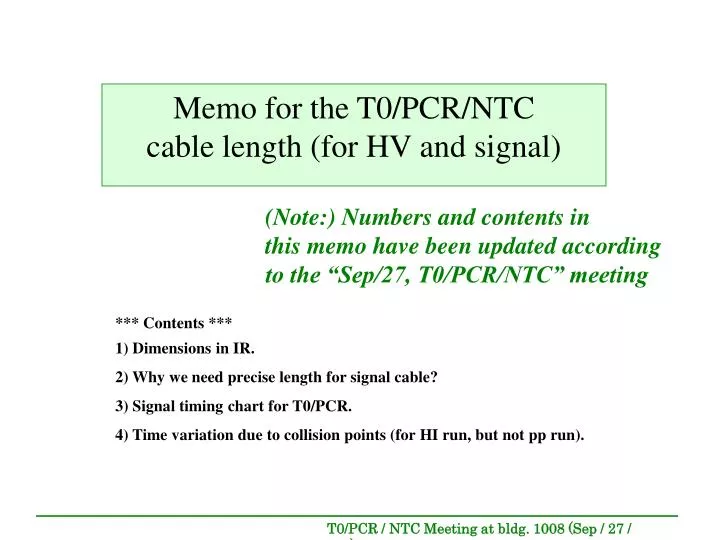
Memo for the T0/PCR/NTCcable length (for HV and signal) (Note:) Numbers and contents in this memo have been updated according to the “Sep/27, T0/PCR/NTC” meeting *** Contents *** 1) Dimensions in IR. 2) Why we need precise length for signal cable? 3) Signal timing chart for T0/PCR. 4) Time variation due to collision points (for HI run, but not pp run).
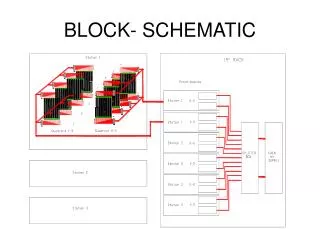
L(Signal C): (“buffer [ns]” [See next page] If 20ns, then 400 cm, i.e. 158 ”) Dimensions in IR(Signal in blue, HV in yellow)(out of scale drawing) L(signal A, ): 169cm (66 ”) S L(HV (A) ): 169cm(66 ”) Patch panel(need to make) ( 16”W12”D4”H, or 12”W6”D no-limint_inH ) Several holes (need to make) One existing 4” hole Nosecone gap L(signal B ): 412cm (162 ”) (FEM) LV power bucket L( HV (B) ): 731cm(288”) BBC (clock fanout) NIM L(Signal D): 214cm (84 ”) (North-South orientation is ** INVERSED(!) ** from the Sep/27presentation) T0/PCR/ NTC/ZDC --Rack-- height: 140cm(55”) width: 61cm(24”) (FEM) E W (clock fanout) HV N LV power bucket Height Depth Width “16 for T0 + 2 for PCR + 8 for NTC + 6spare” sets of Signal (3 length: A+B(RG8,BNC-BNC), C(RG58BNC-BNC), D(RG58BNC-lemo)), and HV (1 length (9m): A+B) is needed.
Why we need precise signal cable length, How to do ?Constraint due to 1 GTM ( Clock is common for BBC, T0, PCR, NTC, and TOF ) “a constant time for clock generation” + 73.25 [ns] ~20[ns] Clock BBC ~44.75 [ns] Signal By following method: (1) The “buffer” [ ns ] is first set to, let’s say, 20ns(4m). (2) Then the “buffer” [ ns ] for T0/PCR must be swapped with fine-tuned length after real pp collision is measured, (in order to fit with in the FEM’s dynamic range(~20ns)). “a constant time for clock generation” +73.25 [ns] + (60.9 - 44.75) [ns] + “buffer” [ns] BECAUSE ~20 [ns] Clock T0,PCR ~ 52.9 (T0) +”buffer” [ns] ~ 60.9 (PCR)+”buffer” [ns] “-5.9” to “+10.6” [ns] Signal “a constant time for clock generation” +ca.262 [ns] ~ (“65to90” + “110”) [ns] Clock TOF ~ 46 [ns] Signal collision
Signal Timing Chart for T0/PCR.(pp collision is assumed to the time zero.) Ts_BBC = 44.75ns Ts_BBC(A)=5.0ns charged particle flight time (for beta=1; 3.33ns/m, 1.5m) Ts_BBC(B)=6nsPMT's transit time Ts_BBC(C)=33.75nscable(RG58 with75cm of 5ns/m, Andrew with 675cm of 4ns/m, and RG58 with 65cm of 5ns/m) ,where Ts_BBC = +Ts_BBC(A) +Ts_BBC(B) +Ts_BBC(C) Ts_T0{PCR} =52.9ns{60.9ns} [-5.9ns,+10.6ns] Note: Dynamic range is ~20 [ns] Ts_T0(A)=1.8ns [- 0.0ns + 4.7ns] charged particle flight time [ nominal value for beta=1; 3.33ns/m, 0.54m] [ variation is: - 0.0ns, and +4.7ns for 0.6GeV/c or +3.6ns for 0.7GeV/c or , of Deuteron] Ts_T0(B) =3.1ns [ + - 3.1 ns ] light velocity up tp PMT cathode {Ts_PCR(B) =11.1ns [ + - 3.1 ns ] light velocity up tp PMT cathode} [ nominal value for 0.5mScintillator 3.1ns/m(80ps/1.3cm)) [ variation is: ±3.1ns, namely, ±0.5mScintillator] Ts_T0(C)=9.5ns [ + - 0.44 ns + - 0.15ns] PMT [nominal value for PMT's Transit Time] [ variation is: ±0.44ns of TTS, ±0.15ns of PMT variations ±0.15ns of pigtail cable variations] Ts_T0(D)=43.2ns [ + - 0.13ns ] cable length [ nominal value for 7.7ns by Pigtail cable with 154cm of 5ns/s, 24.8ns by RG8 with 581cm of 4.27ns/m and 10.7ns by LEMO with 214cm of 5ns/m,] [variation is: the variation of pigtail cable length] Ts_T0(E)=0.0ns [ + - 2.1ns] collision point [ variation is: ±2.1ns(3) for Z±63cm ] ,where Ts_T0 = +Ts_T0(A) +Ts_T0(B) +Ts_T0(C) +Ts_T0(D) +Ts_T0(E) See next page ,where Ts_PCR = +Ts_T0(A) +Ts_PCR(B) +Ts_T0(C) +Ts_T0(D) +Ts_T0(E)
Time variation due to collision points.(for Y2001-HI run, [but not pp run])from online logbook (the plot was shown at RHIC time meeting) 3 gaussian fit y= +p0 * exp ( -0.5 * {(x - p1) / p2} 2 ) +p3 * exp ( -0.5 * {(x - p4) / p5} 2 ) +p6 * exp ( -0.5 * {(x - p7) / p8} 2 ) South North PHENIX RUN LOG Tue Sep 18 02:49:16 2001 by T.Hachiya Run 28282. This was the first RUN after 200MHz RF was used with 56 bunchs. Plots are timing distributions of each side of BBBBC. ZDC scale down factor was already corrected. It is expected to be BBC Z-vertex distribution triggered by inclusive ZDCNS. Au+Au Within ±1(i.e.±0.695ns) : 68.3% Within ±2(i.e.±1.390ns) : 95.5% Within ±3(i.e.±2.085ns) : 99.7% Within ±4(i.e.±2.780ns) : 99.99% Difference Beam gas Beam gas