Download
1 / 28
280 likes | 358 Vues
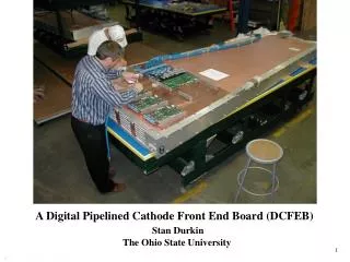
Cathode FE Board. The Ohio State University University of California Davis University of California Los Angeles CERN. Cathode FE Board. Mature Board - Only Small changes over last 3 Years!. MUX. 96 Channels. CMS CLK. Slow control. 7 in. BUCKEYE (ASIC) - amplifies and

E N D
Cathode FE Board The Ohio State University University of California Davis University of California Los Angeles CERN
Cathode FE Board Mature Board - Only Small changes over last 3 Years! MUX 96 Channels CMS CLK Slow control 7 in BUCKEYE (ASIC) - amplifies and shapes input pulse SCA (ASIC) - analog storage for 20 MHz sampled input pulse ADC - events with LVL1ACC digitized and sent to DAQ Motherboard (25 nsec/word) 11.5 in Comparator ASIC - generates trigger hit primitives from shaped pulse Controller FPGA - controls SCA storage and digitization
Cathode FE Board Input/Output Signals
BUCKEYE ASIC Physics Demands ~ 150m ME1/2 ~ 300m MEX/X Rate is demanding 100 KHz/strip 300 KHz track/chamber • 0.8 m AMI CMOS with Linear Capacitor • 5 pole semigaussian • 1 pole 1 zero tail cancellation • 100 nsec peaking time (delta function) • 170 nsec peaking time (real pulse) • Gain .9 mV/fC • Equivalent Noise 1 mV • Nonlinearity < 1 % at 17 MIPS • Rate 3 MIPs at 3 MHz with no saturation • Two track resolution 125 nsec Minuit Fit to Output V(mV) t(nsec)
BUCKEYE (cont.) (noise) ~ Cx20e/pF +4770e
BUCKEYE / SCA BUCKEYE meets all Requirements ! Switched Capacitor Array (SCA) Block Usage (8 caps/block) SCA Specifications - 96 capacitor for each of 16 channels - LVDS addressing read/write - Simultaneous read/write - Gray Code address sequencing - Input impedance < 300 - Non-Linearity (0-2V) 0.25% - Pedestal Cell-Cell variation 0.25 mV - Maximum Sampling rate 20 MHz - Channel-channel access 100 nsec pedestal samples
SCA / Controller FPGA SCA meets design specifications ! AMI 0.8m CMOS Controller FPGA (XILINX Virtex) - does SCA bookkeeping - given LCT set aside 2 blocks of 8 capacitors - generates greycode addressing - controls digitization - given LVL1ACCstarts digitization - multiplexes ADC output to motherboard - digitization take 25 sec - 12 bit ADC 300 KHz LCT 3 KHz L1ACC probability limit <1 error for 125 Hrs Running BLOCKS
Comparator ASIC - 16 channel, 40 MHz output - Input amplified and shaped BUCKEYE output - Generate trigger primitive 1/2 strip hits - Programmable threshold - Programmable timing, working mode = 1.7 mV 0.7m Alcatel J.C. Santiard CERN Efficiency Correct 1/2 strip 90.4 % Nearest N. or Correct 98.3 %
Comparator ASIC ... ASIC Performs to Specifications Highest LHC Rate Removing the Channel Link (3 crossing delay) ... Status - one crossing required to sync signals - prototype has been built and is being tested at Ohio State and UCLA - multiplexer will be rad tested
0 - 5V 10 pF strip 16-ch ASIC 10 pF 16-ch ASIC strip Calibration BUCKEYE has internal shift register which controls calibration JTAG Shift Register Modes Normal Precision Ext. Cap (<1%) Int. Cap Small (1x) Int. Cap Medium (2x) Kill Precision DAQ and Delay on Motherboard Control Pulsing - CCB board generates pseudo pulse, LCT, and LVL1ACC - Precision Ext Cap. Allows gain, linearity, crosstalk, timing measurement. Oscilloscope-like output for each channel. - Any channel can be selectively killed - Trigger logic and thresholds can be checked using small and medium cap small + medium cap medium cap small cap
SCA Capacitor Cell Number Calibration ... Calibration from FNAL Chamber Electronics - 12 bit ADC - 0.5 mV/count 0.54 fC/count - Landau Peak ~ 400 counts - RMS noise for 9216 capacitors RMS Pedestal Width (ADC Counts) Total Noise ~ 1.25 mV ! - linearity for 480 channels System linearity < 1% at 17 MIPs !
Calibration ... 1 % RMS - gain varies ~1% within chip - gain varies ~2% chip to chip Gain Constant Chip Pulser + 137Cs (20 kHz/strip) BUCKEYE can take LHC Rate !
Timing / Slow Control Timing and Synchonization Cathode FE Board allow ±1 Beam Crossing uncertainty on LCT relative to LVL1ACC Timing is a Trigger Issue - FE Board 40 MHz clock has programmable delay on Motherboard - Comparitor 40 MHz clock has programmable delay on CLCT Board - LCT and LVL1ACC synchronized to 40 MHz Clock Interface with Fast and Slow Control Fast Control Signals (CCB) to FE Board - reprogram logic (see rad discussion) - reset logic - pulse, pseudo-LCT, pseudo-LVL1ACC (calibration) Slow Control Signals to FE Board - JTAG signals, TDO,TDI, TCLK, TMS
Slow Control • Slow Control System • one PC (running SCADA CMS slow • control software) serves 24 crates • ethernet 10 Base-T embedded VME • computer • VME Bus within Crate • DAQ Motherboard has VME interface • -FPGA • VME interface generates JTAG for • FE Board Embedded VME Computer: Prototype system achieved 3 Mbit/s loading Spartan FPGA • Cathode FE Board Slow Control • Buckeye Shift Registers • 1 Xilinx EPROM (program and readback) • 1 Xilinx Virtex (readback) • FPGA status checks (check on startup) • comparator thresholds • comparator mode/timing • thermistor (temperature) • access boards unique serial number
Monitoring Each FE Board has a 4 bit Beam Crossing counter - stored in data transferred to Motherboard Each Digitized event has 8 checksum words (CRC15) - stored in data transferred to Motherboard - sensitive to channel link problems LCT-LVL1ACC Coincidence Calculated both on FE Board and Motherboard Separately - motherboard knows when FE data not present - lack of data reported to DAQ FE Boards send fixed data length records to FIFO on Motherboard - motherboard knows when data is missing - lack of data reported to DAQ - CFEB-Motherboard transmission timeout (10 sec) Most failures will be detected before Periodic Radiation reload and resets allowing CCB to Reset the system !
E>100 KeV 1012 1011 Neutron Fluence (cm-2) Neutron Flux (cm-2s-1) ME11 ME11 ME12 ME13 1010 10-6 1 10-3 103 Neutron Energy (MeV) Radius (cm) Radiation Tests Radiation Levels in Endcap Muon Calculations by M. Huhtinen Integrated over 10 LHC years (5x10⁷ s at 1034 cm-2s-1) Neutron Fluence (>100 keV): (0.02 - 6) x 1011 cm-2 Total Ionizing Dose: (0.007 - 1.8) kRad
8 ~12 min exposure Noise vs Dose Gain vs Dose 3000 6 Expected dose in 10 LHC years new runs w/ same chip RMS Noise (mV) Output Amplitude (ADC counts) 4 2000 Curves for all 16 channels 2 1000 0 0 10 20 30 0 100 200 300 Dose (Krad) Dose (Krad) Radiation Tests ... Worst-case Radiation Environment (Use calculated levels times a safety factor of 3) • Measure SEE (SEU and SEL) cross sections for neutron fluence of 2x1012 cm-2 • Measure TID effects up to a dose of 5 kRad • Measure degradation for an equivalent neutron fluence of 2x1012 cm-2
Radiation Test Summary • Fluence = 2.8 x 10¹² / cm2 • Following devices passed the test • LM1117-adj (adjustable voltage regulator) • LM4120-2.5 (voltage reference; 3.3 V, 5 mA) • LM4120-1.8 (voltage reference; 3.3 V, 5 mA) • LM4041 (shunt voltage reference) • SDA321 (Diode Array – reversed biased) • Red LED • AD8011 (300 MHz Current Feedback OpAmp) • Need a rad-tolerant 2.5 V regulator • Good candidate identified. Presently testing.
Radiation Tests ... • Cumulative effects • Total ionization dosage (with 63 MeV protons) • No deterioration of analog performance up to 10 krad • for all three CMOS ASIC’s • All FPGA’s survive beyond dosage of 30 krad • Displacement damage (with 2x1012 cm-2 n’s @ 1 MeV) • Usable voltage regulators and references identified • Protection diodes OK • Single-Event Effects • No latch-up for all ASIC’s up to 2x10¹² p cm-2 • Single Event Upset (SEU) • Cross sections measured for all FPGA’s, C-Links. • All SEU’s in FPGA’s recoverable by reloading SEU Rate on FE Board given by Controller FPGA Controller FPGA (XILINX Virtex) - triple voting logic on crucial gates - SEU cross section 1.7x10⁻¹⁰cm-2 (410,000 s/SEU) Must Reload Virtex Every ~17 minutes
FPGA Reload Scheme EPROM (XC1802) JTAG Reloadable - 2.76x10¹¹p/cm2 37.0 kRad - 3 SEU’s, No Memory Errors - Must reload every 1.5 LHC years ! CCB Program FPGA Reset FPGA EPROM Virtex 5 msec load JTAG Readback FPGA JTAG Program EPROM Readback EPROM Schematic FE Board Loading Reload every 17 minutes or when error is detected Note: Almost all virtex errors will be detected as errors by DAQ system!
Magnetic Field Test FE Board in 3 Tesla Field MRI Facility Ohio State U. Hospital 8 Tesla Field Research Magnet Tested calibration, noise, pedestal, linearity. Only difference was a time shift of 6 nsec Passive Delays - Rhombus LVMDM 100 nsec contain iron have switched to Passive Delays - Data Delay Devices 3D7105 for short delays - Virtex Delay-Lock loops for long delays no difference seen t (nsec) 6 nsec delay
Spark Protection Buckeye Spark Gap 70nH 100 M HV 4.2 KV 1nF 15 100pF anode protection protection circuit chamber Scheme has protected Buckeye for Simulated 3000 Sparks Two Options Under Study 1. Inductor is Chamber- FE Board cable (100 nH/ft) 2. Put 96 Air-core (~68 nH) Inductors on FE Board
Burn-In We have procured a large oven at OSU What do other people do ? CDF: 50-60 C for 8-24 Hrs US Military: 125 C for 320 Hrs • CDF sufficient for things like backward tantalums no sensitivity to semiconductor failure • Replacing boards in CMS forward muon chambers will be difficult We will start conservatively and measure failure rate vs time. Hopefully full US military burn-in will not be needed !
Production • PC boards will be etched and stuffed commercially • ASIC Testing • BUCKEYE Preamp/Shaper • ~ 15000 ASIC chips will be produced by AMI • Bonded in Indonesia by AIT LTD • Tested at Ohio State Measure gain, noise, linearity peaking time, delay time, … for each channel AMI Preproduction 1000 chips Yield ~50% (problem found in one of two AMI assembly lines. They are fixing and will make new samples. Yield increase to >80%) Width 1.6 % channels Gain (ADC Channels)
Production … • SCA ASIC • AMI will manufacture wafers • AMI will measure chips guaranteeing quality • AMI will bond chips • Comparator ASIC • Alcatel will manufacture wafers • an outside company will measure chips • Chips will be bonded in Hong Kong • Alcatel Preproduction • yield 66 % (working on it) • chips are excellent
Production ... Stuffed Boards will be tested and debugged before Burn-In and after Burn-In at O.S.U. Boards will be measured and debugged on computerized tester presently being designed and built at O.S.U. Data Cables - Cables are being assembled and tested by outside companies 9 m skew-clear cable tester
Material Safety FE Board Cables (all board and cable connectors have glass filled Polyester (PBT) rated UL 94-V0 as the insulator) Following CMS Cable Colour Codes: FE Board - Motherboard Cable will beBLUE
Maintenance Ohio State University will maintain the FE Boards 10 % Spare Boards will be Built We anticipate swapping bad boards during accesses and fixing them. Each board has a unique electronic serial number. Swaps can be monitored using software. Click to edit Master title style Conclusion Cathode FE Board Meets All Design Specifiations! It is time to start procuring parts and begin manufacturing...