Download

1 / 71
940 likes | 2.08k Vues
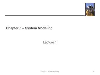
Chapter 5 – System Modeling. Objectives The aim of this chapter is to introduce some types of system model that may be developed as part of the requirements engineering and system design processes. When you have read the chapter, you will:

E N D
Chapter 5 – System Modeling • Objectives • The aim of this chapter is to introduce some types of system model that may be developed as part of the requirements engineering and system design processes. When you have read the chapter, you will: • understand how graphical models can be used to represent software systems; • understand why different types of model are required and the fundamental system modeling perspectives of context, interaction, structure, and behavior; • have been introduced to some of the diagram types in the Unified Modeling Language (UML) and how these diagrams may be used in system modeling; • be aware of the ideas underlying model-driven engineering, where a system is automatically generated from structural and behavioral models. Lecture 1 Chapter 5 System modeling
Topics covered • Context models • Interaction models • Structural models • Behavioral models • Model-driven engineering Chapter 5 System modeling
System modeling • System modeling is the process of developing abstract models of a system, with each model presenting a different view or perspective of that system. • System modeling has now come to mean representing a system using some kind of graphical notation, which is now almost always based on notations in the Unified Modeling Language (UML). • System modelling helps the analyst to understand the functionality of the system and models are used to communicate with customers. Chapter 5 System modeling
Existing and planned system models • Models of the existing system are used during requirements engineering. They help clarify what the existing system does and can be used as a basis for discussing its strengths and weaknesses. These then lead to requirements for the new system. • Models of the new system are used during requirements engineering to help explain the proposed requirements to other system stakeholders. Engineers use these models to discuss design proposals and to document the system for implementation. • In a model-driven engineering process, it is possible to generate a complete or partial system implementation from the system model. Chapter 5 System modeling
System perspectives • A model is an abstraction of the system being studied rather than an alternative representation of that system. • Ideally, a representation of a system should maintain all the information about the entity being represented. • An abstraction deliberately simplifies and picks out the most salient characteristics. • For example, in the very unlikely event of this book being serialized in a newspaper, the presentation there would be an abstraction of the book’s key points. If it were translated from English into Italian, this would be an alternative representation. Chapter 5 System modeling
System perspectives • An external perspective, where you model the context or environment of the system. • An interaction perspective, where you model the interactions between a system and its environment, or between the components of a system. • A structural perspective, where you model the organization of a system or the structure of the data that is processed by the system. • A behavioral perspective, where you model the dynamic behavior of the system and how it responds to events. Chapter 5 System modeling
UML diagram types • UML has become a standard modeling language for object-oriented modeling. • The UML has many diagram types and so supports the creation of many different types of system model. • A survey in 2007 (Erickson and Siau, 2007) showed that most users of the UML thought that five diagram types could represent the essentials of a system Chapter 5 System modeling
UML diagram types • Activity diagrams, which show the activities involved in a process or in data processing . • Use case diagrams, which show the interactions between a system and its environment. • Sequence diagrams, which show interactions between actors and the system and between system components. • Class diagrams, which show the object classes in the system and the associations between these classes. • State diagrams, which show how the system reacts to internal and external events. Chapter 5 System modeling
UML diagram types • The detail and rigor of a model depends on how you intend to use it. There are three ways in which graphical models are commonly used: • As a means of facilitating discussion about an existing or proposed system. • As a way of documenting an existing system. • As a detailed system description that can be used to generate a system implementation. Chapter 5 System modeling
UML diagram types • The purpose of the model is to stimulate the discussion amongst the software engineers involved in developing the system. • The models may be incomplete (so long as they cover the key points of the discussion) and they may use the modeling notation informally. • When models are used as documentation, they do not have to be complete as you may only wish to develop models for some parts of a system. • Models are used as part of a model-based development process, the system models have to be both complete and correct. The reason for this is that they are used as a basis for generating the source code of the system. Chapter 5 System modeling
Use of graphical models • As a means of facilitating discussion about an existing or proposed system • Incomplete and incorrect models are OK as their role is to support discussion. • As a way of documenting an existing system • Models should be an accurate representation of the system but need not be complete. • As a detailed system description that can be used to generate a system implementation • Models have to be both correct and complete. Chapter 5 System modeling
Context models are used to illustrate the operational context of a system - they show what lies outside the system boundaries. This involves working with system stakeholders to decide what functionality should be included in the system and what is provided by the system’s environment. Social and organisational concerns may affect the decision on where to position system boundaries. Architectural models show the system and its relationship with other systems. Context models Chapter 5 System modeling
System boundaries • System boundaries are established to define what is inside and what is outside the system. • They show other systems that are used or depend on the system being developed. • The position of the system boundary has a profound effect on the system requirements. • Defining a system boundary is a political judgment • There may be pressures to develop system boundaries that increase / decrease the influence or workload of different parts of an organization. Chapter 5 System modeling
System boundaries • For example, you are developing the specification for the patient information system for mental healthcare. This system is intended to manage information about patients attending mental health clinics and the treatments that have been prescribed. • In developing the specification for this system, you have to decide whether the system should focus exclusively on collecting information about consultations (using other systems to collect personal information about patients) or whether it should also collect personal patient information. • The advantage of relying on other systems for patient information is that you avoid duplicating data. • The major disadvantage, however, is that using other systems may make it slower to access information. If these systems are unavailable, then the MHC-PMS cannot be used. • The definition of a system boundary is not a value-free judgment. Chapter 5 System modeling
The context of the MHC-PMS Figure 5.1 is a simple context model that shows the patient information system and the other systems in its environment. From Figure 5.1, you can see that the MHC-PMS is connected to an appointments system and a more general patient record system with which it shares data. The system is also connected to systems for management reporting and hospital bed allocation and a statistics system that collects information for research. Finally, it makes use of a prescription system to generate prescriptions for patients’ medication. Chapter 5 System modeling
Process perspective • Context models simply show the other systems in the environment, not how the system being developed is used in that environment. • Process models reveal how the system being developed is used in broader business processes. • UML activity diagrams may be used to define business process models. Activity Diagram: • Activity diagram is another important diagram to describe dynamic behaviour. Activity diagram consists of activities, links, relationships etc. It models all types of flows like parallel, single, concurrent etc. • Activity diagram describes the flow control from one activity to another without any messages. These diagrams are used to model high level view of business requirements. Chapter 5 System modeling
Process model of involuntary detention Figure 5.2 is a model of an important system process that shows the processes in which the MHC-PMS is used. Sometimes, patients who are suffering from mental health problems may be a danger to others or to themselves. They may therefore have to be detained against their will in a hospital so that treatment can be administered. Such detention is subject to strict legal safeguards—for example, the decision to detain a patient must be regularly reviewed so that people are not held indefinitely without good reason. One of the functions of the MHC-PMS is to ensure that such safeguards are implemented. Figure 5.2 is a UML activity diagram. Activity diagrams are intended to show the activities that make up a system process and the flow of control from one activity to another. The start of a process is indicated by a filled circle; the end by a filled circle inside another circle. Rectangles with round corners represent activities, that is, the specific sub-processes that must be carried out. You may include objects in activity charts. In Figure 5.2, the systems that are used to support different processes. These are separate systems using the UML stereotype feature. In a UML activity diagram, arrows represent the flow of work from one activity to another. A solid bar is used to indicate activity coordination. When the flow from more than one activity leads to a solid bar then all of these activities must be complete before progress is possible. When the flow from a solid bar leads to a number of activities, these may be executed in parallel. Figure 5.2, the activities to inform social care and the patient’s next of kin, and to update the detention register Chapter 5 System modeling
Process model of involuntary detention Chapter 5 System modeling
Initial node. The filled in circle is the starting point of the diagram. An initial node isn’t required although it does make it significantly easier to read the diagram. Activity final node. The filled circle with a border is the ending point. An activity diagram can have zero or more activity final nodes. Activity. The rounded rectangles represent activities that occur. An activity may be physical, such as Inspect Forms, or electronic, such as Display Create Student Screen. Flow/edge. The arrows on the diagram. Although there is a subtle difference between flows and edges I have never seen a practical purpose for the difference although I have no doubt one exists. I’ll use the term flow. Fork. A black bar with one flow going into it and several leaving it. This denotes the beginning of parallel activity. Join. A black bar with several flows entering it and one leaving it. All flows going into the join must reach it before processing may continue. This denotes the end of parallel processing. Condition. Text such as [Incorrect Form] on a flow, defining a guard which must evaluate to true in order to traverse the node. Decision. A diamond with one flow entering and several leaving. The flows leaving include conditions although some modelers will not indicate the conditions if it is obvious. Merge. A diamond with several flows entering and one leaving. The implication is that one or more incoming flows must reach this point until processing continues, based on any guards on the outgoing flow. Chapter 5 System modeling
Interaction models • Modeling user interaction is important as it helps to identify user requirements. • Modeling system-to-system interaction highlights the communication problems that may arise. • Modeling component interaction helps us understand if a proposed system structure is likely to deliver the required system performance and dependability. • Use case diagrams and sequence diagrams may be used for interaction modelling. Chapter 5 System modeling
Use case modeling • Use cases were developed originally to support requirements elicitation and now incorporated into the UML. • Each use case represents a discrete task that involves external interaction with a system. • Actors in a use case may be people or other systems. • Represented diagrammatically to provide an overview of the use case and in a more detailed textual form. • Interaction modelling use two approaches; • Use case modelling, which is mostly used to model interactions between a system and external actors (users or other systems). • Sequence diagrams, which are used to model interactions between system components, although external agents may also be included Chapter 5 System modeling
Use case Modelling • Use case modelling is widely used to support requirements elicitation. • A use case can be taken as a simple scenario that describes what a user expects from a system. • Each use case represents a discrete task that involves external interaction with a system. Chapter 5 System modeling
Transfer-data use case • A use case in the MHC-PMS • Figure shows a use case from the MHC-PMS that represents the task of uploading data from the MHC-PMS to a more general patient record system. This more general system maintains summary data about a patient rather than the data about each consultation, which is recorded in the MHC-PMS. Chapter 5 System modeling
Tabular description of the ‘Transfer data’ use-case Chapter 5 System modeling
Use cases in the MHC-PMS involving the role ‘Medical Receptionist’ Chapter 5 System modeling
Use case Example’ Chapter 5 System modeling
Sequence diagrams • What is a UML Sequence Diagram? • Sequence diagrams describe interactions among classes in terms of an exchange of messages over time. • A sequence diagram shows actors, objects (instances of classes) and the messages sent between them Chapter 5 System modeling
Sequence diagrams • Sequence diagrams are part of the UML and are used to model the interactions between the actors and the objects within a system. • A sequence diagram shows the sequence of interactions that take place during a particular use case or use case instance. • The objects and actors involved are listed along the top of the diagram, with a dotted line drawn vertically from these. • Interactions between objects are indicated by annotated arrows. Chapter 5 System modeling
Sequence diagram for View patient information Chapter 5 System modeling
Sequence diagram for View patient information 1. The medical receptionist triggers the ViewInfo method in an instance P of the PatientInfo object class, supplying the patient’s identifier, PID. P is a user interface object, which is displayed as a form showing patient information. 2. The instance P calls the database to return the information required, supplying the receptionist’s identifier to allow security checking (at this stage, we do not care where this UID comes from). 3. The database checks with an authorization system that the user is authorized for this action. 4. If authorized, the patient information is returned and a form on the user’s screen is filled in. If authorization fails, then an error message is returned. Chapter 5 System modeling
Sequence diagram for Transfer Data Second example of a sequence diagram from the same system that illustrates two additional features. These are the direct communication between the actors in the system and the creation of objects as part of a sequence of operations. 1. The receptionist logs on to the PRS. 2. There are two options available. These allow the direct transfer of updated patient information to the PRS and the transfer of summary health data from the MHC-PMS to the PRS. 3. In each case, the receptionist’s permissions are checked using the authorization system. 4. Personal information may be transferred directly from the user interface object to the PRS. Alternatively, a summary record may be created from the database and that record is then transferred. 5. On completion of the transfer, the PRS issues a status message and the user logs off Chapter 5 System modeling
Sequence diagram for Transfer Data Chapter 5 System modeling
Structural models • Structural models of software display the organization of a system in terms of the components that make up that system and their relationships. • Structural models may be static models, which show the structure of the system design, or dynamic models, which show the organization of the system when it is executing. • You create structural models of a system when you are discussing and designing the system architecture. • Structural model: a view of an system that emphasizes the structure of the objects, including their classifiers, relationships, attributes and operations Chapter 5 System modeling
Class diagrams • Class diagrams are used when developing an object-oriented system model to show the classes in a system and the associations between these classes. • A class diagram is a UML structural diagram. Depending on the complexity of a system, you can use a single class diagram to model the entire system, or you can use several class diagrams to model the components of the system. • Class diagrams are the blueprints of your system. Use class diagrams to model the objects that make up the system, to display the relationships between the objects, and to describe what those objects do • An object class can be thought of as a general definition of one kind of system object. • An association is a link between classes that indicates that there is some relationship between these classes. • When you are developing models during the early stages of the software engineering process, objects represent something in the real world, such as a patient, a prescription, doctor, etc. Chapter 5 System modeling
UML classes and association • Figure 5.8 is a simple class diagram showing two classes: Patient and Patient Record with an association between them. • In Figure 5.8, I illustrate a further feature of class diagrams—the ability to show how many objects are involved in the association. • In this example, each end of the association is annotated with a 1, meaning that there is a 1:1 relationship between objects of these classes. That is, each patient has exactly one record and each record maintains information about exactly one patient. Chapter 5 System modeling
Classes and associations in the MHC-PMS • You can define that an exact number of objects are involved or, by using a *, as shown in Figure 5.9, that there are an indefinite number of objects involved in the association. • Figure 5.9 develops this type of class diagram to show that objects of class Patient are also involved in relationships with a number of other classes. In this example, I show that you can name associations to give the reader an indication of the type of relationship that exists. • The UML also allows the role of the objects participating in the association to be specified. • When showing the associations between classes, it is convenient to represent • these classes in the simplest possible way. • To define them in more detail, you add information about their attributes (the characteristics of an object) and operations (the things that you can request from an object). • For example, a Patient object will have the attribute Address and you may include an operation called ChangeAddress, which is called when a patient indicates that they have moved from one address to another. Chapter 5 System modeling
Classes and associations in the MHC-PMS Chapter 5 System modeling
The Consultation class • In the UML, you show attributes and operations by extending the simple rectangle that represents a class. • The figure shows following • 1. The name of the object class is in the top section. • 2. The class attributes are in the middle section. This must include the attribute names and, optionally, their types. • 3. The operations (called methods in Java and other OO programming languages) associated with the object class are in the lower section of the rectangle. • Figure shows possible attributes and operations on the class Consultation. In this example, assume that doctors record voice notes that are transcribed later to record details of the consultation. • To prescribe medication, the doctor involved must use the Prescribe method to generate an electronic prescription. Chapter 5 System modeling
Key points • A model is an abstract view of a system that ignores system details. Complementary system models can be developed to show the system’s context, interactions, structure and behavior. • Context models show how a system that is being modeled is positioned in an environment with other systems and processes. • Use case diagrams and sequence diagrams are used to describe the interactions between users and systems in the system being designed. Use cases describe interactions between a system and external actors; sequence diagrams add more information to these by showing interactions between system objects. • Structural models show the organization and architecture of a system. Class diagrams are used to define the static structure of classes in a system and their associations. Chapter 5 System modeling
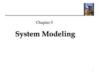
Chapter 5 – System Modeling Lecture 2 Chapter 5 System modeling
Generalization • Generalization is an everyday technique that we use to manage complexity. • Rather than learn the detailed characteristics of every entity that we experience, we place these entities in more general classes (animals, cars, houses, etc.) and learn the characteristics of these classes. • This allows us to infer that different members of these classes have some common characteristics e.g. squirrels and rats are rodents. Chapter 5 System modeling
Generalization • In modeling systems, it is often useful to examine the classes in a system to see if there is scope for generalization. If changes are proposed, then you do not have to look at all classes in the system to see if they are affected by the change. • In object-oriented languages, such as Java, generalization is implemented using the class inheritance mechanisms built into the language. • In a generalization, the attributes and operations associated with higher-level classes are also associated with the lower-level classes. • The lower-level classes are subclasses inherit the attributes and operations from their superclasses. These lower-level classes then add more specific attributes and operations. Chapter 5 System modeling
A generalization hierarchy The UML has a specific type of association to denote generalization, as illustrated in Figure 5.11. The generalization is shown as an arrowhead pointing up to the more general class. This shows that general practitioners and hospital doctors can be generalized as doctors and that there are three types of Hospital Doctor—those that have just graduated from medical school and have to be supervised (Trainee Doctor); those that can work unsupervised as part of a consultant’s team (Registered Doctor); and consultants, who are senior doctors with full decision making responsibilities. Chapter 5 System modeling
A generalization hierarchy with added detail In a generalization, the attributes and operations associated with higher-level classes are also associated with the lower-level classes. The lower-level classes are subclasses inherit the attributes and operations from their super classes. These lower-level classes then add more specific attributes and operations. For example, all doctors have a name and phone number; all hospital doctors have a staff number and a department but general practitioners don’t have these attributes as they work independently. They do however, have a practice name and address. This is illustrated in Figure which shows part of the generalization hierarchy that have extended with class attributes. The operations associated with the class Doctor are intended to register and de-register that doctor with the MHC-PMS. Chapter 5 System modeling
An aggregation model shows how classes that are collections are composed of other classes. Aggregation models are similar to the part-of relationship in semantic data models. Objects in the real world are often composed of different parts. For example, a study pack for a course may be composed of a book, PowerPoint slides, quizzes, and recommendations for further reading. Sometimes in a system model, you need to illustrate this. Object class aggregation models Chapter 5 System modeling
The aggregation association • The UML provides a special type of association between classes called aggregation that means that one object (the whole) is composed of other objects (the parts). • To show this, we use a diamond shape next to the class that represents the whole. The figure shows that a patient record is a composition of Patient and an indefinite number of Consultations. Chapter 5 System modeling
Behavioral models • Behavioral models are models of the dynamic behavior of a system as it is executing. They show what happens or what is supposed to happen when a system responds to a stimulus from its environment. • You can think of these stimuli as being of two types: • Data Some data arrives that has to be processed by the system. • Events Some event happens that triggers system processing. Events may have associated data, although this is not always the case. Chapter 5 System modeling
Behavioral models • For example, a phone billing system will accept information about calls made by a customer, calculate the costs of these calls, and generate a bill to be sent to that customer. • By contrast, real-time systems are often event driven with minimal data processing. For example, a landline phone switching system responds to events such as ‘receiver off hook’ by generating a dial tone, or the pressing of keys on a handset by capturing the phone number, etc. Chapter 5 System modeling
Data-driven modeling • Many business systems are data-processing systems that are primarily driven by data. They are controlled by the data input to the system, with relatively little external event processing. • Data-driven models show the sequence of actions involved in processing input data and generating an associated output. • They are particularly useful during the analysis of requirements as they can be used to show end-to-end processing in a system. • Data-driven models were amongst the first graphical software models. • Data-flow diagrams (DFDs) as a way of illustrating the processing steps in a system. • Data-flow models are useful because tracking and documenting how the data associated with a particular process moves through the system helps analysts and designers understand what is going on. • Data-flow diagrams are simple and intuitive and it is usually possible to explain them to potential system users who can then participate in validating the model. Chapter 5 System modeling
Order processing Chapter 5 System modeling