Download
1 / 5
50 likes | 162 Vues
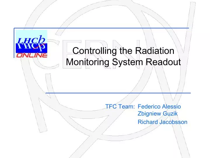
Controlling the Radiation Monitoring System Readout. Federico Alessio Zbigniew Guzik Richard Jacobsson. TFC Team:. Sharing the knowledge. 1U LINUX PC with USB interface same configuration as LINUX PC to control clock distribution cards

E N D
Controlling the Radiation Monitoring System Readout Federico Alessio Zbigniew Guzik Richard Jacobsson TFC Team:
Sharing the knowledge • 1U LINUX PC with USB interface • same configuration as LINUX PC to control clock distribution cards • just needed to copy driver, libraries and server to publish services and commands to PVSS • created a “RMS” PVSS project with TFC-alike libraries • 3U CAEN V830 module: 32 ch latching scaler • VME protocol • 32 independent LVDS input connected to 32 counters • 32k MultiEvent Buffer (FIFO) to store countings • synchronized counting • 3U CAEN V1718 module: VME-USB bridge that acts as a crate controller • same model used in the clock distribution crate (RF2TTC & RFRx boards) in TFC LHCb Note 2007-062 24/11/08
Dedicated control system • Monitoring of the particles rates for each of the RMS sensor • Monitoring of left/right and up/down rate asymmetries • Controlling settings of the scaler: enabling/disabling channels, modification of internal latching counter, modification of 32-bit data protocol • Generation of warning and alarm messages • Monitoring/correction of the ChI baseline and/or background conditions • Background subtraction • Online data presentation • Offline data storage for offline analysis (archiving) 24/11/08
RMS for background • RMS mostly thought of in terms of IT accumulated dose monitoring, but the online background capabilities should be exploited: • Time resolution: the control system resolution (data in memory in scaler server polling the request data available in PVSS control panel) could be quantified in roughly O(10 ms), which corresponds to ~110 LHC turns. What is the requested time resolution? • i.e. 1s is surely suitable for accumulated dose, while 10 ms is better for online background. • Sensitivity: considering the location, which type of background the RMS would be sensitive to and what type of machine effects? Needed simulation to estimate real value… 24/11/08
An estimate Considering the conversion factor 100 Hz = 1 pA and a 10:1 ratio between SEE and δ-e, we expect roughly 25 kHz of frequency counting as calibration baseline At LHC max luminosity (with no radiation), the hadron rate integrated over the IT RMS area is within 8*10^6 and 8*10^7 Hz per channel/sensor We expect a counting rate increase within 100Hz and 1 kHz per channel (1.6*10^-7 pA*s ~10 pA 1 kHz ) • The readout system resolution is assumed to be 10ms, so we expect an average of ~10 Hz in counting rate per “update” with nominal rate. In a “live monitoring”, with a 10 ms update interval: • what would be the best threshold over which it is necessary to produce an alarm? • do we need to be sensitive to the 10^9 range (1pA = 1kHz for lighter doses)? 24/11/08