Download

1 / 20
490 likes | 1.13k Vues
Power Factor and Power Factor Correction. Learning Objectives. Define power factor. Define unity, leading and lagging power factors. Define power factor correction and unity power factor correction.

E N D
Learning Objectives • Define power factor. • Define unity, leading and lagging power factors. • Define power factor correction and unity power factor correction. • Calculate the inductor or capacitor value required to correct AC series parallel networks to the desired apparent power. • Compare currents, voltages, and power in AC series parallel networks before and after power factor correction.
Review AC Power to a Resistive LoadAC Power to a Inductive LoadAC Power to a Capacitive Load
Review Apparent Power • For a load with voltage V and current I, the power that “appears to flow” to the load is VI where V and I are rms values. S = VI (VA) • S is called the apparent power and has units of volt-amperes (VA).
Review Real and Reactive Power • The power triangle also shows that we can find real (P) and reactive (Q) power.
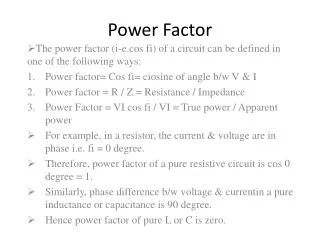
Power Factor • Power factor (FP) tells us what portion of the apparent power (S) is actually realpower (P). • Power factor is a ratio given by FP = P / S • Power factor is expressed as a number between 0 to 1.0 (or as a percent from 0% to 100%)
Power Factor • From the power triangle it can be seen that FP = P / S = cos • Power factor angle is thus given = cos-1(P / S) • For a pure resistance, = 0º • For a pure inductance, = 90º • For a pure capacitance, = -90º NOTE: Ө is the phase angle of ZT, not the current or voltage.
Example Problem 1 Determine the power factor for this circuit. Is it inductive or capacitive?
Example Problem 2 For the circuit below, determine PT, QT, ST, FP and draw the power triangle. If E is 120VRMS, determine the supply current IRMS.
Unity power factor (FP = 1) • Implies that all of a load’s apparent power is real power (S = P). • If FP = 1, then = 0º. • It could also be said that the load looks purely resistive. • Load current and voltage are in phase.
Lagging power factor ( > 0º) • The load current lags load voltage • Implies that the load looks inductive.
Leading power factor ( < 0º) • The load current leads load voltage • Implies that the load looks capacitive.
Why is Power Factor Important? • Consider the following example: A generator is rated at 600 V and supplies one of two possible loads.Load 1: P = 120 kW, FP = 1Load 2: P = 120 kW, FP = 0.6 • How much current (I) is the generator required to supply in each case?
Why is Power Factor Important? • For the load with Fp= 0.6, the generator had to supply 133 more amperes in order to do the same work (P)! • Larger current means larger equipment (wires, transformers, generators) which cost more. • Larger current also means larger transmission losses (think I2R).
Why is Power Factor Important? • Because of the wide variation in possible current requirements due to power factor, most large electrical equipment is rated using apparent power (S) in volt-amperes (VA) instead of real power (P) in watts (W). • Is it possible to change the power factor of the load?
Power Factor Correction • In order to cancel the reactive component of power, we must add reactance of the opposite type. This is called power factor correction.
Power Factor Correction • In practice, almost all loads (commercial, industrial and residential) look inductive (due to motors, fluorescent lamp ballasts, etc.). • Hence, almost all power factor correction consists of adding capacitance.
Example Problem 3 The 600 V, 120 KVA generator is connected to a load with P = 120 kW and QL = 160 kVAR. • Determine the power factor of the load. • Determine the size (in VAR) of capacitive load (QC) required to correct the power factor to unity.
Power Factor Correction • Transmission lines and generators must be sized to handle the larger current requirements of an unbalanced load. • Industrial customers are frequently fined by the utility if their power factor deviates from the prescribed value established by the utility.
Example Problem 4 Determine S, PT, QT, and FP. Determine the value of the capacitance (in F) required to bring the power factor up to unity (freq of 60 Hz). Determine generator current before and after correction.