Download
1 / 41
410 likes | 623 Vues
CARMA. Dick Plambeck UC Berkeley (for the CARMA consortium) www.mmarray.org URSI, 24 June 2003, Columbus, Ohio. Berkeley-Illinois-Maryland Assn. array 10 6.1-m diameter antennas. Caltech array 6 10.4-m antennas. + UChicago SZA 8 3.5-m antennas. OVRO

E N D
CARMA Dick Plambeck UC Berkeley (for the CARMA consortium) www.mmarray.org URSI, 24 June 2003, Columbus, Ohio
Berkeley-Illinois-Maryland Assn. array 10 6.1-m diameter antennas Caltech array 6 10.4-m antennas + UChicago SZA 8 3.5-m antennas
OVRO D. Woody S. Scott J. Lamb D. Hawkins J. Carpenter A. Sargent G. Blake N. Scoville people project manager: Tony Beasley Berkeley • D. Plambeck • M. Wright • A. Bolatto • C. Kraybill • M. Fleming • L. Blitz • W.J. Welch Maryland • M. Pound • P. Teuben • K. Rauch • S. Vogel • L. Mundy • A. Harris Illinois • R. Plante • D. Mehringer • L. Snyder • R. Crutcher • L. Looney + programmers, engineers, technicians, postdocs, graduate students
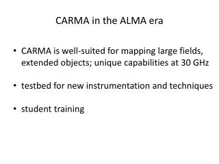
antennas 3 different antenna diameters - a heterogeneous array • exploit new algorithms for mosaicing, high fidelity imaging • sensitive to wide range of spatial frequencies; image large objects
BIMA mosaic of M33 • CO 1-0 115 GHz • 759 pointing centers
BIMA mosaic of M33(Engargiola et al. 2003) • 148 GMCs detected • overlie HI filaments (HI image: Deul & van der Hulst 1987)
receivers for the 1mm and 3mm bands: • 4 GHz bandwidth, 1 polarization at first light • continuum sensitivity: 2-3 mJy/beam, in 1 minute • 230 GHz brightness sensitivity: 1 K for 1 km/sec channel, 1'' beam, in 1 hour
site selection and acquisition requirements: • within 60 minute drive of existing OVRO infrastructure • elevation 7000-9000 ft for good atmospheric transmission but low snow load • 400-m diameter flat area, + baselines to 2 km • avoid environmental battles all such sites are in Inyo National Forest, require Environmental Impact Report
OVRO Juniper Flat environmental studies done for 2 sites Cedar Flat
Cedar Flat: 20 min drive to OVRO on paved road, maintained (and plowed) by Caltrans simulated antenna Highway 168
225 GHz Percentiles 25% < 0.12 50% < 0.16 75% < 0.28
BIMA antenna move • keep dish and feed legs in one piece • move 9 antennas in 8 weeks
OVRO antennas will be dismantled to pass through “the narrows”
array configurations • 5 antenna configurations, approx 55 pads • 2 km max baseline
Cedar FlatE-array(most compact)synth beam 4.5" at 230 GHz array center
BIMA antennas within collision range SZA provides even shorter spacings combine with single dish measurements from 10.4-m antennas to recover all spatial frequencies E-array
A-array synthesized beam, declination –30 0.26 × 0.14" FWHM 5% contours
BIMA A-array detection of a stellar flare in Orion ( 86 GHz,synthesized beam 0.9 × 0.5" ) 20 Jan 2003 4 UT 20 Jan 2003 8 UT 30 mJy 150 mJy BN IRc2
use common transporter for 6-m and 10-m antennas avoid ‘custom’ vehicle 50% of weight on tow vehicle for traction antenna transporter
transporter tow vehicle: 6-wheel drive military truck (Oshkosh MTVR)
fiberoptics • all communication with antennas via 8 singlemode optical fibers • use standard SMF 28 fiber - length change with temperature is 1 part in 105 • use BIMA round trip phase measuring system to monitor fiber lengths
diurnal changes in fiber length (BIMA data from July 2002) fiber lengths Sun hits fibers • 135’ of fiber at outdoor air temp ( = 200 nsec) • ~ 2 psec/C • ~ 180°/C at 230 GHz outdoor air temp
synth cpl laser TRX fiber 1 cpl RX phslck ref MXR RX fiber 2 BIMA round trip phase measurement advantage: no electronics at the antenna, just a fiber coupler disadvantage: lengths of fibers 1 and 2 must track with temperature and flexure (requires loose tube fiber)
Caltech COBRA correlator • based on FPGAs, not custom correlator chips • 4 GHz bandwidth • 256 channels, 20 MHz resolution • 15 baselines
CARMA first light correlator • uses COBRA hardware design • 15 telescopes, 105 baselines • 8 independent sections: • may be positioned anywhere in 4 GHz IF band • choose 2, 8, 31, 62, 125, 250, or 500 MHz bandwidth • velocity resolution 0.04 to 40 km s-1/ channel at 1.3 mm separateSZA correlator: 8 antennas, 28 baselines, 8 GHz bandwidth
COBRA: each board handles 5 baselines, 500 MHz/baseline, 32 chans/baselineCARMA: reprogram FPGAs to handle 10 baselines, add spectral line capability
Leslie Looney pulling underground fiber for long baselines John Carlstrom repairing the Air Products refrigerator on receiver 3