Download
1 / 34
340 likes | 348 Vues
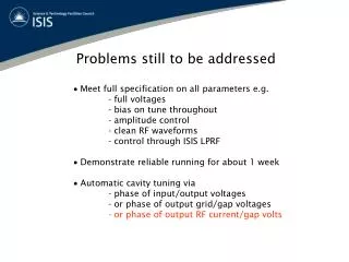
Design Features: still to be determined and open questions. P. Ferracin. 4 th Joint HiLumi LHC-LARP Annual Meeting November 17-21, 2014 KEK, Tsukuba. Outline. Cable and coil design fine tuning Splicing Magnet length, axial support, and connection box Quench protection

E N D
Design Features:still to be determined and open questions P. Ferracin 4th Joint HiLumiLHC-LARP Annual Meeting November 17-21, 2014 KEK, Tsukuba
Outline P. Ferracin • Cable and coil design fine tuning • Splicing • Magnet length, axial support, and connection box • Quench protection • Support structure
Extracts from MQXF conductor review close-outs P. Ferracin
Extracts from MQXF conductor review close-outs P. Ferracin
Cable and coil design fine tuning P. Ferracin • Design parameters updates under consideration • Cable geometry • PIT cable to be updated and RRP fine tuning under consideration (from conductor review) • Coil cross-section changes to account for • Effect of mechanical deformation on field quality • Effect of 3D end effects on integrated field harmonics • Random/systematic errors • Magnetic length • Increase of margin (from conductor review) ? • End spacers
Cable and coil design fine tuning (I) Baseline 0.55 keystone 0.150 mm ins. 0.4 keystone 0.145 mm ins. P. Ferracin • For PIT, reduction of keystone angle from 0.55 to 0.4 deg., with same cable mid-thickness, under consideration • Thin/thick edge 0.025 mm thicker/thinner • Cross-section as close as possible to baseline • Still, new wedges, poles and spacers • 8-9 months from cable geometry definition to beginning of winding
Cable and coil design fine tuning (II) • Effect of mechanical deformation on field quality • Effect of 3D end effects on integrated field harmonics P. Ferracin
Cable and coil design fine tuning (III) • How do we fine tune field quality during production? • Low order un-allowed harmonics • Magnetic shimming • Allowed harmonics • Fiberglass shim in poleand/or mid-plane included during winding curing? • With 0.100 mm shim 4-5 µm reduction of space for expansion out of 70 µm • And the b14 (-0.67 units)? P. Ferracin
Cable and coil design fine tuning (IV) P. Ferracin • Possible increase of magnetic length to increase margin • Example • from 140 to 130 T/m 7% decrease in Gnom • Coil length • +308 mm in Q1/Q3 (half unit) • +525 mm in Q2
Cable and coil design fine tuning (V) P. Ferracin • End spacers and end-shoes • Roxie and BEND designs • At the moment, no major issues observed by visual inspection • Next steps: cut coils and magnet test
Cable and coil design fine tuning: when? 2014 2015 2016 2017 2018 RRP short model 1, MQXFS1 and MQXFS2 CERN schedule PIT short model 1, MQXFS4 RRP short model 2, MQXFS5 RRP prototype 1, MQXFP1 PIT prototype 1, MQXFP2 P. Ferracin
Cable and coil design fine tuning: when? 2014 2015 2016 2017 2018 RRP short model 1, MQXFS1 and MQXFS2 RRP short model 2, MQXFS3 LARP schedule RRP prototype 1, MQXFP1 RRP prototype 2, MQXFP2 RRP prototype 3, MQXFP3 P. Ferracin
Outline P. Ferracin • Cable and coil design fine tuning • Splicing • Magnet length, axial support, and connection box • Quench protection • Support structure
Splice operation at CERNBy J.C. Perez The same tooling is used for tinning and splicing using MOB 39 as flux and solder 96/4 Tin/Silver The S2-Glass insulation is removed and the cable cleaned on both sides Nb3Sn cable tinning operation Cutting of the Nb3Sn cable and splicing of the NbTi Leads P. Ferracin • Nb3Sn soldered to Nb-Ti and Cu stabilizer
Splice operation at BNLBy J. Schmalzle P. Ferracin • Materials: • Double Nb-Ti extension lead. • Pre-assembled into pairs using separate fixture. • Solder - 96/4 Tin Silver ribbon. • Flux - MOB-39 (CERN approved). • Procedure outline: • Remove saddle extensions. • Saddles remain in place. • Fold back interlayer insulation. • Remove cable insulation. • Clean leads with wire brush, alcohol. • Remove last few mandrel blocks. • Mid-plane shims stay in place, help support leads. • Pre-tin coil lead using lead solder fixture (with spacer). • Open fixture, clean, inspect and trim tinned lead. • Solder tinned lead to tinned extension pair using lead solder fixture (without spacer).
Pre or Post-impregnation wire soldering • CERN • After impregnation, instrumentation wires and Quench heaters powering leads are soldered to the trace • pockets filled using Eco-bond cured at room temperature • LARP • Short wires soldered to trace before impregnation (~150 mm long wires). • Layers of fiberglass cloth added to fill wiring pocket. • Wires packed in Silicone putty. • Inside the impregnation fixture. • After impregnation, wires are extended by making an inline splice solder joint. P. Ferracin
Outline P. Ferracin • Cable and coil design fine tuning • Splicing • Magnet length, axial support, and connection box • Quench protection • Support structure
MQXF magnet design Magnetic length of short model P. Ferracin
MQXF magnet design P. Ferracin • From magnetic length to end of magnet (end-plate + connection box) • Connection side: 510 mm • Non-connection side: 214 mm
Q1 P. Ferracin • Connection side: from magnetic length to end of end-cover • 301.5+238.5=540 mm (510 mm magnetic to end of magnet in MQXF) • Non-connection side: from magnetic length to Q1a-Q1b “middle point” • 186.5+63.5=250 mm (214 mm magnetic to end of magnet in MQXF)
Q2 P. Ferracin • Connection side: from magnetic length to end of end-cover • 325+234=559 mm (510 mm magnetic to end of magnet in MQXF) • Non-connection side: from magnetic length to Q1a-Q1b “middle point” • 172+78=250 mm (214 mm magnetic to end of magnet in MQXF)
Minimum distance between Q1a and Q1b magnetic lengths P. Ferracin • From magnetic length to end of magnet (end-plate + connection box) • Non-connection side: 220 mm • Minimum distance: ~ 440 mm • The 500 mm distance between the magnetic lengths is compatible with the present design of the MQXF magnet.
Q1-Q2-Q3 connection side P. Ferracin • From magnetic length to end-cover • 559 mm in current lay-out • 510 mm magnetic to end of magnet in short model • Lyra and end-cover • Additional ~200 mm 759 mm • TBD • bus-bars inside or outside cold mass • More compact LE end plate • Nuts on the RE?
Connection boxFirst iteration P. Ferracin, M Juchno, J.C. Perez • Top and bottom support plate • Instrumentation plate • 2 plates for connections
Connection boxSecond iteration P. Ferracin Both easy-way and hard-way bent cables More compacted option under investigation
Outline P. Ferracin • Cable and coil design fine tuning • Splicing • Magnet length, axial support, and connection box • Quench protection • Support structure
Quench protection baseline scenario Paolo Ferracin • Protection studied in the case of 2 magnets in series (16 m) protected by one dump resistor (48 mΩ, 800 V maximum voltage) • Voltage threshold: 100 mV • Cu/Non-Cu: 1.2 • Validation time: 10 ms • Protection heaters on the outer and on the inner layer • Hot spot T with 1.2 Cu/Non-Cu ratio: ~263 K • Negligible effect of ~6-7 K from RRR (100-200) and Cu/non-Cu ratio (1.1 to 1.2)
Inner layer quench heaters vs. CLIQ (I) P. Ferracin • Perforated polyimide • 18% of stainless steel • 32% of holes, 1 mm diameter • 50% polyimide 0.05 mm thick
Inner layer quench heaters vs. CLIQ (II)CLIQ to be validated in HQ03 and MQXFS P. Ferracin
Inner layer quench heaters vs. CLIQ (II)CLIQ to be validated in HQ03 and MQXFS P. Ferracin
Outline P. Ferracin • Cable and coil design fine tuning • Splicing and soldering of instrumentation wires • Magnet length, axial support, and connection box • Quench protection • Support structure
Support structure modification P. Ferracin • Shell segments • From ½ + ½ • to ¼ + ½ + ¼ • Laminated structure? • No issues for yokes • Impact on assembly for collar and pads • Cost • Still under consideration • Reduction of parts (master incorporated into the pads)
Support structureTBDs Aluminium Plate Longitudinal groove for gas protection (second trial) Stainless steel samples to be welded Stainless steel backing strip (first trail) P. Ferracin • LHe containment • Dimensions of SS shell, tack welding blocks and backing strip
Support structureTBDs P. Ferracin • Cold bore tube and beam screen • Current baseline scenario • Insertion of cold bore tube in cold mass without beam screen • Features in coil poles to guide and support are needed • Insertion of beam screen after cold testing, before installation