Download
1 / 1
10 likes | 111 Vues
Hydrologic Topology Francisco Olivera, Ph.D., P.E. – Assistant Professor ( folivera@civilmail.tamu.edu ) Srikanth Koka – Graduate Research Assistant ( srikanth@tamu.edu ) Texas A&M University – Department of Civil Engineering - College Station, Texas.

E N D
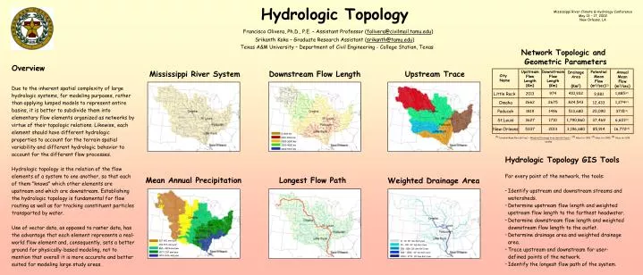
Hydrologic Topology Francisco Olivera, Ph.D., P.E. – Assistant Professor (folivera@civilmail.tamu.edu) Srikanth Koka – Graduate Research Assistant (srikanth@tamu.edu) Texas A&M University – Department of Civil Engineering - College Station, Texas Mississippi River Climate & Hydrology Conference May 13 – 17, 2002 New Orleans, LA Network Topologic and Geometric Parameters Overview Due to the inherent spatial complexity of large hydrologic systems, for modeling purposes, rather than applying lumped models to represent entire basins, it is better to subdivide them into elementary flow elements organized as networks by virtue of their topologic relations. Likewise, each element should have different hydrologic properties to account for the terrain spatial variability and different hydrologic behavior to account for the different flow processes. Hydrologic topology is the relation of the flow elements of a system to one another, so that each of them "knows" which other elements are upstream and which are downstream. Establishing the hydrologic topology is fundamental for flow routing as well as for tracking constituent particles transported by water. Use of vector data, as opposed to raster data, has the advantage that each element represents a real-world flow element and, consequently, sets a better ground for physically-based modeling, not to mention that overall it is more accurate and better suited for modeling large study areas. Mississippi River System Downstream Flow Length Upstream Trace Upstream Flow Length (Km) Downstream Flow Length (Km) Potential Mean Flow (m3/sec)(1) Drainage Area (Km2) Annual Mean Flow (m3/sec) City Name 974 410,932 1,885(2) Little Rock 2013 9,881 Omaha 2662 2675 824,543 1,274(2) 12,433 Paducah 1819 1496 513,680 20,090 3715(3) St.Louis 1,790,860 3627 1710 37,469 6,601(2) New Orleans 5337 2013 3,196,680 85,914 16,772(4) 0-1000 Km 1000-2000 Km (1) Potential Mean Flow (m3/sec) = Weighted Drainage Area (mm Km2/year) , (2) Value for 1999, (3) Value for 2000, (4) Value for 1995 2000-3000 Km 31,555 3000-4000 Km 4000-5242 Km Hydrologic Topology GIS Tools For every point of the network, the tools: • Identify upstream and downstream streams and watersheds. • Determine upstream flow length and weighted upstream flow length to the farthest headwater. • Determine downstream flow length and weighted downstream flow length to the outlet. • Determine drainage area and weighted drainage area. • Trace upstream and downstream for user-defined points of the network. • Identify the longest flow path of the system. Mean Annual Precipitation Longest Flow Path Weighted Drainage Area 527-801 mm/year 0 – 10 106 mm Km2/year 252-526 mm/year 10 – 100 106 mm Km2/year 802 – 1076 mm/year 100 – 500 106 mm Km2/year 1077-1351 mm/year 500 – 1000 106 mm Km2/year 1352-1626 mm/year 1000 – 2711 106 mm Km2/year