Download
1 / 43
430 likes | 737 Vues
2. 設計方法 Design Methods and Requirements. - Structural Design Process - Building Codes - Working Stress Design - Strength Design Method - Dead Load and Live Load - Load Transfer in Structure. Architectural Functional Plans. Final Design. Detailing. Structural System. Connection

E N D
2 設計方法 Design Methods and Requirements - Structural Design Process - Building Codes - Working Stress Design - Strength Design Method - Dead Load and Live Load - Load Transfer in Structure
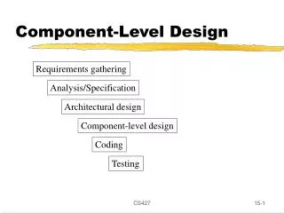
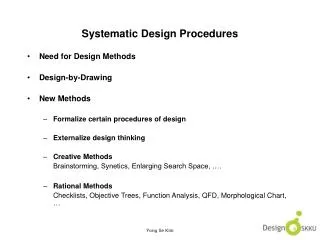
Architectural Functional Plans Final Design Detailing Structural System Connection Design Trial Sections OK Revise Sections NG Acceptable? Modeling Analysis Member Design Structural Design Process
結構之定義 • 係指在一力系作用下,能將力傳於其他物體而維持平衡者,稱之為結構。
結構之功能 • 承擔結構體本身重量及外力,並限制結構體產生之變形。
力與變位 • 力:指力與力偶。 • 變位:指移動與轉動。
結構分析之目的 • 結構應力分析依觀點之不同,可分為彈性分析與塑性分析。其目的則在於: • 決定結構各部分因外力作用所產生之力,包括支承反力,及各構件之內力等。(外力:計有荷重、溫度變化、材料收縮、預力等) • 求得結構控制點之變位,及其與相應力間之關係。
描述結構行為之基本定律 • 力之平衡(equilibrium of forces) • 變位之諧和(compatibility of displacements) • 力與變位之關係(force-displacement relationship)
線性結構 • 力與變位之間呈線性關係,則此結構稱為「線性結構」,且適用疊合原則。線性關係之成立,應滿足下列條件: • 結構之材料為彈性,且在載重範圍內遵循虎克定律。 • 結構之變形甚小,於計算力與應力時,可不計是項變形,而仍遵原結構形狀進行。
方法 未知數 解題用的方程式 未知的係數 力法 力 贅力作用點之諧和性、力-位移關係 柔度係數 位移法 位移 結點之平衡方程式、力-位移關係 勁度係數 結構分析之方法 • 力法(force method)或柔度法(flexibility method)。 • 位移法(displacement method)或勁度法(stiffness method)。
力法之矩陣表示式 D:外力作用點依外力方向之位移 Dr:贅力作用點之位移 F:外力 Fr:贅力 H:柔度矩陣
位移法之矩陣表示式 D:位移 F:作用力 S:勁度矩陣
3D Solid Elements - Application III: Bridges The Brno-Vienna Expressway Crossing, Czech
3D Solid Elements - Application I: Bridges The Brno-Vienna Crossing - F.E. Model
結構設計程序 1.結構系統的決定 2.設計規範與資料之收集 3.繪製結構配置圖 4.結構桿件尺寸與材質的決定 5.載重分析 6.應力分析 7.桿件設計 8.校核桿件應力或變形 9.繪製詳細圖與製造圖、統計材料、開材料規範與購料
結構設計程序 1.結構系統的決定 通常必須配合結構物的用途與功能,優良的結構系統能以最經濟的建造費用達到安全之目的。 2.設計規範與資料之收集 結構體依其功能、材質有各種不同的設計規範與準則。設計之基本資料如設計載重及容許基礎載重等。 3.繪製結構配置圖 依結構物之預定建地及功能,繪製結構配置圖。 4.結構桿件尺寸與材質的決定 進行結構分析前,必須先假設各桿件的尺寸,才能計算其勁度。但各種結構體其跨度、高度等均不同,因此桿件尺寸須依相關規範及設計者實計際經驗做判斷。
結構設計程序 5.載重分析 一般包括垂直載重及水平載重。垂直載重又可分為靜載重與活載重;水平載重則為風力、土壓力、地震力等。 6.應力分析 結構物所承受的載重有垂直載重及水平載重,由於這些載重之作用,使構架中的桿件產生了應力(包括軸力、撓曲應力、剪力、扭力等),而如何求得這些應力即所謂的應力分析。 7.桿件設計 根據應力分析所得資料,並依照相關設計規範進行桿件設計。包括板、樑、柱、牆及基礎的設計。 8.校核桿件應力或變形 校核桿件的應力與變形是否符合規範要求或限制,若不符合,則須重新假設桿件尺寸,做局部修正或重新分析並設計之。 9.繪製詳細圖與製造圖、統計材料、開材料規範與購料
設計基準 • 設計之基本要求:設計強度 需要強度 即[強度折減因數][計算強度] [載重因數][使用載重]
什麼是ASD 與LRFD • ASD (Allowable Steel Design)一般稱為容許應力設計法,使用這種分法設計會得到較為保守的結構,但是相對的會增加成本,因為根據 AISC 9th Edition 的規範,使用鋼材的力量, 對於拉應力而言只用到降伏力量的 60% , 對於空間桁架而言的結構, 使用此種方法是正確的. • LRFD (Load and Resistance Factor Design)一般稱為極限應力設計法(載重及強度係數設計法) ,這種設計的方法,會使結構達到較為經濟,整體的可靠性昇高. 使用到鋼材的極限拉力並以負載組合的係數加以調整.對於纖維膜結構而言, 使用此種方法是正確的.
R SF Q ALLOWABLE STRESS DESIGN (ASD) Where : Q = load R = nominal strength of material SF = safety factor
ASD之設計基準 ASD:Fb=0.66Fy
Q Rn LOAD & RESISTANCE FACTOR DESIGN (LRFD) Where : = load factor = reduction factor Q = load Rn = nominal strength of material
機率模式 • 安全係數及載重因子是為了考量在設計過程中所存在的不定性及變化性。結構設計乃包含了二個隨機變數Q及R的關係,若R<Q時,則極限狀態成立。 • 一種合適的結構設計是允許存在極小機率的極限狀態發生。然而,Q及R的實際機率分佈並不確知,只有其中平均值Qm及Rm,與標準偏差δQ及δR是可得知的。
可靠度指數β之定義 • 如圖所示,吾人即可決定使用構材設計之相對可靠度,圖中所示之分部曲線為ln(R/Q),當ln(R/Q) ≦ 0時,極限狀態即發生,圖中斜線部分即為極限狀態發生之機率。當統計數據Rm、Qm、δR、δQ為已知,且βσln(R/Q) = ln(R/Q)m,那麼在ln(R/Q) ≦ 0之條件下的面積是決定β值的變化,β值可概約地以下式表之: 其中 VR=δR/Rm偏差係數 VQ=δQ/Qm載重偏差係數 β為可靠度指數
SAFETY PROVISIONS • 1. Overloaded probability covered by Load Factor • U = 1.2 D + 1.6 L • = 1.05 (D + LR E) • = 0.9 D E • = 0.75 (1.2 D+1.6 L+1.6 W) etc…. • 2. Understrength probability covered by Reduction Factor • Bending without axial load = 0.80 • Axial Tension = 0.80 • Axial Compression • conventional stirrup = 0.65 • spiral stirrup = 0.70 • Shear and Torsion = 0.60
3. Reasons for Safety Factor Necessity • Variability in Strength • a. Variability of concrete strength & steel reinforcement • b. Actual dimension design dimension • c. Simplification of Assumptions • Variability in Loading • Consequences of Collapse • a. Loss of human life • b. Loss of material, time, ...... • c. Cost of renovation and re-built
Risk of Various Activities 10-3Motorcycle racingAvoidable risks connected Miningwith daring people = 10-3 per year Automobile travel 10-4 Swimming Avoidable risk connected Airplane travel with careful people = 10-4 per year Fire in Building 10-5 PoisoningUnavoidable risk : Structural collapse = 10-5 per year 10-6 Lightning 10-7 10-8 Vaccinations
40 Minimum specified 30 Number 20 10 60 66 72 78 84 90 54 Yield Stress (Ksi) VARIABILITY IN STRENGTH Distribution of steel yield stress for grade 60 reinforcement (Allen 1972)
80 70 • • • • • • • • • • • Yield Strength (Ksi) • 60 • • 50 4 5 6 7 8 9 10 14 18 3 Bar Size • • • • • • • • VARIABILITY IN STRENGTH - Cont´d. Variation in mill test yield strength with bar size grade 60 reinforcement (Grant 1976)
57.4 60 N = 1844 x = 0.06 in = 0.28 in Range = 2.25 in 50 40 Frequency (%) 30 20 15.8 12.9 6.2 10 3.0 2.3 1.8 0.2 0.3 0.1 -0.5 0 0.5 1.0 -1.0 X = Deviation from size on drawings - Cont´d. VARIABILITY IN STRENGTH Difference between actual widths of columns and the sizes shown on drawings. (Tso and Zelman 1970)
40 Minimum specified for any bar Minimum specified for any lot of bars 30 Number 20 10 0.94 0.96 0.98 1.00 1.02 1.04 1.06 Area / Nominal Area - Cont´d. VARIABILITY IN STRENGTH Ratio of actual bar area to nominal area (Allen 1972)
40 40 35 35 30 30 25 Number of Columns (%) 25 Average = 1.01 Average = 0.98 Number of Beams (%) 20 20 15 15 10 10 5 5 0.8 0.9 1.0 1.1 1.2 1.3 0.6 0.7 0.8 0.9 1.0 1.1 1.2 Mtest / Mcalc Ptest / Pcalc - Cont´d. VARIABILITY IN STRENGTH Comparison of strengths calculated using rectangular stress block to strength measured in laboratory tests. (Mattock et al.1961)
Recommendation Codes: ACI: American Concrete Institute (ACI318-95) UBC: Uniform Building Code Building Codes
From Working Stress Design (WSD) To Ultimate Strength Design (USD) Early 1900s to early 1960s: WSD was mainly used. 1956 ACI code (ACI 318-56): USD was first introduced. ACI 318-63: Treated WSD and USD on equal basis. ACI 318-71: Based entirely on strength approach (USD) WSD was small part called Alternate Design Method (ADM). ACI 318-77: ADM moved to Appendix A USD was called Strength Design Method. ACI 318-83: ADM moved to Appendix B ACI 318-89: ADM back to Appendix A ACI 318-95: ADM still in Appendix A but Unified Design Provision was introduced in Appendix B ACI 318-01: ? ? ?
Allowable stress Fa Stress from service load Disadvantages: - No provision for reliability of loads Dead Load & Live Load - Creep and Shrinkage not included in calculation - Stress not proportion to strain at failure F.S. is not known - Design under service load condition - Apply F.S. to strength of materials for allowable stress level Fa Working Stress Design (WSD) Alternate Design Method Concrete: Fa= 0.45f’c (ACI), 0.375 f’c Steel: Fa= 0.50Fy
Design Strength Required Strength (U) where Design Strength = Strength Reduction Factor (f) ด Nominal Strength Strength Design Method (SDM) Ultimate Stress Design (USD) Strength Reduction Factor = factor that account for (1) Variations in material strengths and dimensions (2) Inaccuracies in the design equations (3) Degree of ductility and required reliability of member (4) Importance of member in the structure
Strength reduction factor (f) : Bending f = 0.90 Shear and Torsion f = 0.85 Compression f = 0.70 or 0.75 Nominal Strength (N) = Strength of a member calculated using Strength Design Method. Required Strength (U) = Load Factors ด Service load = Factored Load Dead Load Factor = 1.4 Live Load Factor = 1.7 Factored Load = 1.4 DL + 1.7 LL Service Load = DL + LL
General: U = 1.4 DL + 1.7 LL Wind Load: U = 0.75(1.4 DL + 1.7 LL+1.7W) U = 1.05DL + 1.275W Lateral Earth Pressure: U = 1.4 DL + 1.7 LL+1.7H U = 0.9DL + 1.7H Factored Load Combinations
Dead Loads Material Load Unit Plain Concrete 2,323 kg/m3 Steel 7,850 kg/m3 Reinforced Concrete 2,400 kg/m3 Roof Truss 10-30 kg/m2
Live Loads 1) Floor Loads 2) Snow and Ice: 50 - 200 kg/sq.m 3) Rain: ponding effect 4) Traffic Loads for Bridges 5) Impact Loads: Vibration 6) Lateral Loads: - Wind Loads - Earthquake Loads
Load Transfer in Structure Snow, Rain, Wind and Construction load Floor loads Roof + Dead load Slab + Dead load Wall load Beam + Dead load Wind load Column + Dead load Foundation