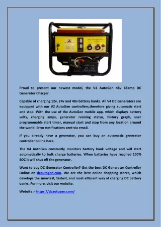
Download
1 / 31
471 likes | 982 Vues
Fundamental of Electrical Engineering. DC GENERATORS. Semester II 09/10. Fundamental of Electrical Engineering. DC generators : dc machines used as generator. Five major types of dc generators, classified according to the manner in which their field flux is produced:.

E N D
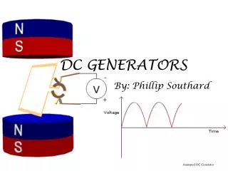
Fundamental of Electrical Engineering DC GENERATORS Semester II 09/10
Fundamental of Electrical Engineering DC generators : dc machines used as generator. Five major types of dc generators, classified according to the manner in which their field flux is produced: • Separately excited generator: In separately excited generator, the field flux is derived from a separately power source independent of the generator itself. • Shunt generator: In a shunt generator, the field flux is derived by connecting the field circuit directly across the terminals of the generators. • Series generator: In a series generator, the field flux is produced by connecting the field circuit in series with the armature of the generator. • Cumulatively compounded generator: In a cumulatively compounded generator, both a shunt and series field is present, and their effects are additive. • Differentially compounded generator: In differentially compounded generator: In a differentially compounded generator, both a shunt and a series field are present, but their effects are subtractive. Semester II 09/10
Fundamental of Electrical Engineering DC Generators • These various types of dc generator differ in their terminal (voltage-current) characteristic, and the application is depending to which is suited. • DC generators are compared by their voltages, power ratings, efficiencies and voltage regulations: Semester II 09/10 +VR = Drooping characteristics -VR = Rising characteristic
Equivalent Circuit of DC Generators The equivalent circuit of a DC generator A simplified equivalent circuit of a DC generator, with RF combining the resistances of the field coils and the variable control resistor
Fundamental of Electrical Engineering Separately Excited Generator Semester II 09/10 Fig : Separately excited DC generator A separately excited DC generator is a generator whose field current is supplied by a separately external DC voltage source VT = Actual voltage measured at the terminals of the generator IL = current flowing in the lines connected to the terminals. EA = Internal generated voltage. IA = Armature current.
Fundamental of Electrical Engineering The Terminal Characteristic of A Separately Excited DC Generator Semester II 09/10 The terminal characteristic of a separately excited dc generator (a) with and (b) without compensating windings (EA = K) Take note about the axes between motors ( and ind) and generators (VT and IL) • For DC generator, the output quantities are its terminal voltage and line current. The terminal voltage is VT = EA – IARA (IA = IL) • Since the internal generated voltage EA is independent of IA, the terminal characteristic of the separately excited generator is a straight line.
Fundamental of Electrical Engineering The Terminal Characteristic of A Separately Excited DC Generator • When the load is supplied by the generator is increased, IL (and therefore IA) increase. As the armature current increase, the IARA drop increase, so the terminal voltage of the generator falls. (Figure (a) PREVIOUS SLIDE) • This terminal characteristic is not always entirely accurate. In the generators without compensating windings, an increase in IAcauses an increase in the armature reaction, and armature reaction causes flux weakening. This flux weakening causes a decrease in EA = Kω which further decreases the terminal voltage of the generator. The resulting terminal characteristic is shown in Figure (b) PREVIOUS SLIDE) Semester II 09/10
Fundamental of Electrical Engineering Control of Terminal Voltage • If DC Motors we control torque-speed, in DC Generator we control VT • The terminal voltage of a separately excited DC generator can be controlled by • changing the internal generated voltage EAof the machine. • VT = EA – IARA • If EA increases, VT will increase, and if EA decreases, VT will decreases. Since the internal generated voltage, EA = KΦω, there are two possible ways to control the voltage of this generator: • Change the speed of rotation. If ω increases, then EA = KΦω increases, so VT = EA - IARA increases too. • Change the field current. If RF is decreased, then the field current increases • (IF =VF/RF ). Therefore, the flux Φ in the machine increases. As the flux rises, EA= Kω must rise too, so VT = EA – IARA increases. Semester II 09/10
Fundamental of Electrical Engineering The Shunt DC Generator A shunt DC generator : DC generator that supplies its own field current by having its field connected directly across the terminals of the machine. Semester II 09/10 Because of generator supply it own field current, it required voltage buildup Figure : The equivalent circuit of a shunt DC generator.
Fundamental of Electrical Engineering Voltage Buildup in A Shunt Generator • Assume the DC generator has no load connected to it and that the prime mover starts to turn the shaft of the generator. The voltage buildup in a DC generator depends on the presence of a residual flux in the poles of the generator. • This voltage is given by Semester II 09/10 • This voltage, EA (a volt of two appears at terminal of generators), and it causes a current IF to flow in the field coils. This field current produces a magnetomotive force in the poles, which increases the flux in them. • EA, then VT increase and cause further increase IF, which further increasing the flux and so on. • The final operating voltage is determined by intersection of the field resistance line and saturation curve. This voltage buildup process is depicted in the next slide
Fundamental of Electrical Engineering Voltage buildup occurred in discrete steps Semester II 09/10 EA may be a volt or two appear at the terminal during start-up
Fundamental of Electrical Engineering • Several causes for the voltage to fail to build up during starting which are : • Residual magnetism. If there is no residual flux in the poles, there is no Internal generated voltage, EA = 0V and the voltage will never build up. • Critical resistance. Normally, the shunt generator builds up to a voltage determined by the intersection of the field resistance line and the saturation curve. If the field resistance is greater than critical resistance, the generator fails to build up and the voltage remains at the residual level. To solve this problem, the field resistance is reduced to a value less than critical resistance. • Refer Figure 9-51 page 605 (Chapman) Semester II 09/10 Critical resistance
Fundamental of Electrical Engineering • The direction of rotation of the generator may have been reversed, or the connections of the field may have been reversed. In either case, the residual flux produces an internal generated voltage EA. The voltage EA produce a field current which produces a flux opposing the residual flux, instead of adding to it. • Under these conditions, the flux actually decreases below res and no voltage can ever build up. Semester II 09/10
Fundamental of Electrical Engineering The Terminal Characteristic of a Shunt DC Generator Semester II 09/10 Figure : The terminal characteristic of a shunt dc generator • As the load on the generator is increased, IL increases and so IA = IF + IL also increase. An increase in IA increases the armature resistance voltage drop IARA, causing VT= EA -IARA to decrease. • However, when VT decreases, the field current IF in the machine decreases with it. This causes the flux in the machine to decrease; decreasing EA. Decreasing EA causes a further decrease in the terminal voltage, VT = EA - IARA
Fundamental of Electrical Engineering Voltage Control for Shunt DC Generator • There are two ways to control the voltage of a shunt generator: • Change the shaft speed, ωm of the generator. • Change the field resistor of the generator, thus changing the field current. • Changing the field resistor is the principal method used to control terminal • voltage in real shunt generators. If the field resistor RF is decreased, then the • field current IF = VT/RF increases. • When IF , the machine’s flux , causing the internal generated voltage • EA. EA causes the terminal voltage of the generator to increase as well. Semester II 09/10
Fundamental of Electrical Engineering The Series DC Generator Figure : The equivalent circuit of a series dc generator Semester II 09/10 • A series DC generator is a generator whose field is connected in series with its armature. Because the field winding has to carry the rated load current, it usually have few turns of heavy wire. • Clear distinction, shunt generator tends to maintain a constant terminal voltage while the series generator has tendency to supply a constant load current. • The Kirchhoff’s voltage law for this equation :
Fundamental of Electrical Engineering Terminal Characteristic of a Series Generator Figure : A series generator terminal characteristic with large armature reaction effects Semester II 09/10 • The magnetization curve of a series DC generator looks very much like the magnetization curve of any other generator. At no load, however, there is no field current, so VT is reduced to a very small level given by the residual flux in the machine. As the load increases, the field current rises, so EA rises rapidly. The IA (RA + RS) drop goes up too, but at the first the increase in EA goes up more rapidly than the IA(RA + RS) drop rises, so VT increases. After a while, the machine approaches saturation, and EA becomes almost constant. At that point, the resistive drop is the predominant effect, and VT starts to fall.
Fundamental of Electrical Engineering The Cumulatively Compounded DC Generator Figure : The equivalent circuit of a cumulatively compounded DC generator with a long shunt connection Semester II 09/10 A cumulatively compounded DC generator is a DC generator with bothseries and shunt fields, connected so that the magnetomotive forces from the two fields are additive.
Fundamental of Electrical Engineering The Cumulatively Compounded DC Generator The total magnetomotive force on this machine is given by Fnet = FF + FSE - FAR where FF = the shunt field magnetomotive force FSE = the series field magnetomotive force FAR = the armature reaction magnetomotive force NFI*F = NFIF + NSEIA - FAR Semester II 09/10
Fundamental of Electrical Engineering The other voltage and current relationships for this generator are Semester II 09/10
Fundamental of Electrical Engineering Another way to hook up a cumulatively compounded generator. It is the “short-shunt” connection, where series field is outside the shunt field circuit and has current IL flowing through it instead of IA. Semester II 09/10 Figure : The equivalent circuit of a cumulatively DC generator with a short shunt connection
Fundamental of Electrical Engineering The Terminal Characteristic of a Cumulatively DC Generator • When the load on the generator is increased, the load current IL also increases. • Since IA = IF + IL, the armature current IA increases too. At this point two effects • occur in the generator: • As IA increases, the IA (RA + RS) voltage drop increases as well. This tends to cause a decrease in the terminal voltage, VT = EA –IA (RA + RS). • As IA increases, the series field magnetomotive force FSE = NSEIA increases too. This increases the total magnetomotive force Ftot = NFIF + NSEIA which increases the flux in the generator. The increased flux in the generator increases EA, which in turn tends to make VT= EA – IA (RA + RS) rise. Semester II 09/10
Fundamental of Electrical Engineering Voltage Control of Cumulatively Compounded DC Generator • The techniques available for controlling the terminal voltage of a cumulatively • compounded DC generator are exactly the same as the technique for controlling the • voltage of a shunt DC generator: • Change the speed of rotation. An increase in causes EA = K to increase, increasing the terminal voltage VT = EA – IA (RA + RS). • Change the field current. A decrease in RF causes IF = VT/RF to increase, which increase the total magnetomotive force in the generator. As Ftot increases, the flux in the machine increases, and EA = K increases. Finally, an increase in EA raises VT. Semester II 09/10
Fundamental of Electrical Engineering Analysis of Cumulatively Compounded DC Generators The equivalent shunt field current Ieq due to the effects of the series field and armature reaction is given by Semester II 09/10 The total effective shunt field current is
Fundamental of Electrical Engineering Field Resistance IA (RA + RS) Semester II 09/10 VT at no load condition will be the point at which the resistor line and magnetization curve intersect. As load is added to the field current Ieq and the resistive voltage drop [IA(RA + RF)]. The upper tip triangle represents the internal generated voltage EA. The lower line represents the terminal voltage VT
The Differentially Compounded DC Generator The equivalent circuit of a differentially compounded DC generator A differentially compounded DC generator is a generator with both shunt and series fields, but this time their magnetomotive forces subtract from each other.
Fundamental of Electrical Engineering The Differentially Compounded DC Generator The net magnetomotive force is Fnet = FF – FSE – FAR Fnet = NFIF – NSEIA - FAR And the equivalent shunt field current due to the series field and armature reaction is given by : Semester II 09/10 The total effective shunt field current in this machine is or
Fundamental of Electrical Engineering Voltage Control of Differentially Compounded DC Generator • Two effects occur in the terminal characteristic of a differentially compounded • DC generator are • As IA increases, the IA (RA + RS) voltage drop increases as well. This increase tends to cause the terminal voltage to decrease VT. • As IA increases, the series field magnetomotive FSE = NSEIA increases too. This increases in series field magnetomotive force reduces the net magnetomotive force on the generator, (Ftot = NFIF – NSEIA), which in turn reduces the net flux in the generator. A decrease in flux decreases EA, which in turn decreases VT. • Since both effects tend to decrease VT, the voltage drop drastically as the load is increased on the generator as shown in next slide Semester II 09/10
Fundamental of Electrical Engineering Semester II 09/10
Fundamental of Electrical Engineering Voltage Control of Differentially Compounded DC Generator • The techniques available for adjusting terminal voltage are exactly the same as • those for shunt and cumulatively compounded DC generator: • Change the speed of rotation, m. • Change the field current, IF. Semester II 09/10
Fundamental of Electrical Engineering END OF CHAPTER 2 Semester II 09/10