Download
1 / 50
540 likes | 886 Vues
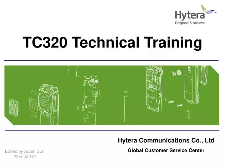
TC320 Technical Training. Hytera Communications Co., Ltd Global Customer Service Center. Edited by Adam Sun 22Feb2012. Content. Main Function & Feature Technical Specification Software & Setting Disassembly & Re-assembly Circuit D escription & Analysis Basic Troubleshooting.

E N D
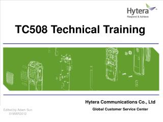
TC320 Technical Training Hytera Communications Co., Ltd Global Customer Service Center Edited by Adam Sun 22Feb2012
Content • Main Function & Feature • Technical Specification • Software & Setting • Disassembly & Re-assembly • Circuit Description & Analysis • Basic Troubleshooting
Main Function & Feature TC320 is a economy/business two-way radio which spread to the world in 2008 with different marketing requirement. Itis unique for its compact and delicate size, and the ergonomically design will give you an exceptional experience of portability, deliver you secure, instant and reliable communications at peak efficiency.
Main Function & Feature • Fine shape fashion • TC-320 smooth lines, ultra-thin appearance, with the mechanical design of the human body works. As a result of the use of mitigation for a long time and have a sense of fatigue. The whole production with battery and antenna, weighs about 135g. • Easy one-hand operation • TC-320 with the fine and streamlines body, use power switches and buttons to adjust the volume. Feel very good channel knob and PPT button, users can ensure that a signal basic walkie-talkie in one-hand operation. • Mini USB socket programming/charging • TC-320 with a mini-USB interface, through HYT dedicated date lines, it can be achieved to TC-320 charge and direct programming.
Main Function & Feature • Scramble • Compander • Power display • High / Low Power switch • Channel spacing adjustable • Monitor • VOX • USB socket-charge/programming • Auto-saving feature • Electricity shortage warning • Busy channel lock • Launch time-out timer • Computer Programming • Wire clone
Technical Specification Description of positive /negative electrode Positive electrode Negative electrode Negative electrode Negative electrode Positive electrode for charging power
Technical Specification CV voltage specification and adjustment Notes: There is only one communal VCO for TX/RX while adjusting CV voltage. When adjust TC101, we need pay attention to TX CV voltage and RX CV voltage at same time. After adjustment, we should cover the hole with copper sheet.
Technical Specification Specification and adjustment for TX Notes: It should have a inductive test while testing the whole radio, the specification as above. TX output power for PCB testing is2.0W/0.5W, the TX current≤1.4A/0.8A.
Technical Specification Specification and adjustment for RX Notes: Due to external interference ,the squelch level voltage range has some deviation.
Software & Setting Programming Software Description In user mode, we can set some function and parameters via programming software in PC, the operation is as following: Install the programming software of TC320 in PC Connect the TC-320 and PC with the programming cable, one side is USB interface of PC, the other side is Mini USB socket of TC320 Turn on the radio Open the programming software, and read the data from the TC320 Notes: If the radio enter the “READ” successfully, it will glitter red light, after having done it, it will extinguish red light; if the radio enter the “WRITE” successfully, it will glitter green light, after having done it , it will extinguish with green light. During the course of programming, if there is some abnormal case or no response, it show that the programming is failure, and the PC will alert some wrong information.
Software & Setting Programming Software Description The programming software of TC-320 is the same with TC-518. Programming software latest version: HT518-320-310E-V1.01.16. Its download address: http://www.hytera.cn/dl/index.aspx?rid=47&uid=6362&tid=1&url=/Service/HT518-320-310E-V1.01.16(Programming software).zip
Software & Setting After install the programming software of TC320, click “Model” --- “Model information” ,we can select the corresponding radio type and frequency range, then can do some operations such as “READ” or “ WRITE”.
Software & Setting From the function of “Buttons/Keypad”, we can set the corresponding function of “SK1”, a new function of “Channel Lock” can be set here.
Software & Setting Notes: Do not enable the function of “panel test mode” and “factory clone mode”.
Software & Setting From “Per Channel”, we can set some parameters such as “frequency , power level, CTCSS/CDCSS” etc.
Software & Setting From the “Per personality” , we can set some special parameters of “ TX/RX”
Software & Setting From “Scan”, we can set some parameters for scan personality
Software & Setting Wire Clone Mode • The operation of wire clone mode • Connect the master radio and slave radio with clone cable, press “SK” key of master radio and turn on the radio, after 2 seconds, it will enter wire clone mode, just turn on the slave radio, it also will enter wire clone mode • In wire clone mode , we can switch user clone mode to factory clone mode via pressing “SK” key ( we should enable “factory clone mode” in programming software , or we can not switch it ) • While press “PTT” key , the data from master radio will clone to slave radio, after finish it ,we can continue to clone other radios • The indication of wire clone mode • The LED will glitter red light while cloning, and it will glitter green light after finish cloning; • Slave radio:the LED will glitter green light and it will go out green light after finish cloning • The difference between “factory clone mode” and “ user clone mode” • User clone mode: only can clone the related data ( such as frequency , CTCSS etc.) in user mode, it will not clone the adjusted frequency , baseband parameters etc. • Factory clone mode: it will clone all data except “series number” • Notice • If the clone cable is not good contact, it will cause error • If the LED flash red light while cloning, the master radio will alert low voltage emergency, but the data will not stop cloning
Disassembly & Reassembly Components Description
Disassembly & Reassembly Components Description
Disassembly & Reassembly Disassemble Radio • Turn off the radio • Remove the antenna • Remove the battery • Push the battery latch upward. • Remove the battery cover • Take out the battery from the bottom
Disassembly & Reassembly Disassemble Radio • Disassemble the channel selector knob and nut, waterproof ring. • Remove the channel selector cover • Remove the nut • Remove the channel selector knob • Remove the nut and waterproof ring Channel selector cover Channel selector knob Nut and waterproof ring
Disassembly & Reassembly Disassemble Radio • Disassemble the back case and side PTT cover • Remove the four screws from the back case. • Push the back case upwards • Pull out the back case • Take out the side PTT cover
Disassembly & Reassembly Disassemble Radio • Disassemble PCB • Remove the 2 screws from the PCB • Remove the steady ring from the PCB and the channel selector switch • Pay attention to the speaker line and charge pole of back case
Disassembly & Reassembly Reassemble Radio • Reassemble PCB • Reassemble the MIC cover • Make sure the speaker is good contact, the installation of charge pole in back case is normal • Install the steady ring of channel selector switch and put the PCB inside it • Screw the two screws MIC cover Speaker cable Reassemble the model cover Steady ring of channel selector Install the screw Install ST1. 7X4 screws in the PCB
3 1 2 Disassembly & Reassembly Reassemble Radio • Reassemble back case • Reassembly the side PTT cover • Take out the sponge and put it to right place. • Screw the four screws Install 4pcs PT2.0*8.0mm screws in sequence PTT cover
Disassembly & Reassembly Reassemble Radio • Reassemble the top nut and cover • Install the waterproof ring to the nut • Install the nut with the waterproof ring to the main unit, and screw it tightly with a cross sleeve • Install the channel selector knob • Screw the fixed screws • Install the channel selector knob cover Waterproof ring Installation direction Channel Selector Knob 5 Screw the fixed screws Take out the protect paper. Install the cover matching the marked point 图13
Disassembly & Reassembly Reassemble Radio 5 Reassemble the antenna Install the battery and battery cover Note Stick copper foil
Circuit Description & Analysis 1. RF Parts 1.1 PLL PLL circuit generates the first local oscillator for reception and the RF signal for transmission PLL circuit diagram
Circuit Description & Analysis 1. RF Parts 1.2 RF power amplifier The demodulated carrier signal which output from VCO is pre-amplified by U501 and amplified by Q401, Q402, Q403, the amplified RF signal will be filtered by LPF to remove unwanted signal and send to antenna.Q404, Q405 and U401 are composed of APC, U401 is used to control the bias voltage of driving transistor Q402 and power amplifier FET Q403 so as to control transmitting current. RF power amplifier circuit diagram
Circuit Description & Analysis 1. RF Parts 1.3 RX The input signal from antenna is filtered by acoustic wave filter to remove unwanted signal and amplified by Q506,then enter the high frequency /low noise filter of U501 for amplifying ,the amplified signal will be second mixed, demodulated, filtered, de-emphasis, decode and D-A switch and get audio signal. Receiving circuit diagram
Circuit Description & Analysis 2. MCU/Signal processing and audio amplifier
Circuit Description & Analysis 2. MCU/Signal processing and audio amplifier • 2.1 MCU • The control circuit is composed of MCU, EEPROM. • The main function of MCU: data’s transmitting and store; checking the signal of external pressing keys, VOX-DET and process; control and switch receive /transmit; open/close the squelch circuit; output a controlling signal to control high/low switch circuit, audio amplifier circuit, VCO power supply circuit, receiving power supply circuit and transmitting power supply circuit. • 2.2 Signal process • Transmitting baseband process • Receiving baseband process • 2.3 Audio amplifier • The audio signal out from U601 is processed and amplified by audio amplifier IC(U301) and drive the speaker to get audio.
Circuit Description & Analysis 3. Power Supply Power Supply Diagram The power supply of 3.7V which controlled and switched by U602 and get two line 3V DC, one is VCC for CPU, the other 3V to VT and VR under the controlling of V-SAVE, also it supply V-SAVE to PLL.
Basic Troubleshooting Can not power on No voice or abnormality voice while powering on No /low TX power No Rx/low receiving sensitivity Unlock while powering on Can not charge normally
Basic Troubleshooting Can not power on Steps Check the battery capacity is full and the battery plate is well contact with the main unit Check the power switch is broken Check whether pin6 of AVR IC U602 is 3V output Check the crystal 32.768KHz for CPU is broken Check the reset IC U605 is broken? Check the pins of CPU is falsely-soldering Power switch AVRU602 Reset IC U605 32.768KHz CPU falsely-soldering
Basic Troubleshooting 6. Basic Troubleshooting No voice or abnormal voice while powering on Steps Check speaker, speaker line’s soldering is normal Check speaker socket is broken Check audio power amplifier IC U301(AP4890)is normal Audio power amplifier The soldering of speaker line Speaker socket
Basic Troubleshooting No/low TX power Steps Check the output voltage of Q601 Check TX current Check the bias voltage of final power amplifier Check the output voltage of pin4 for U501 Check power amplifier while there is current but no TX power. Check power supply for TX circuit while there is no current no power. about 3.7V about1.0V Final PA RQA0002 U501 Q601
Basic Troubleshooting No RX/low Receiving Sensitivity Steps Check the crystal of band pass filter is broken Check filter 450KHz is loose or broken Check the first mixer Q505 is broken Check the IF processing of IC U501 is falsely-soldering or broken Check the demodulator is loose or broken IF IC U501 1st Mixer Q505 450 Filter Crystal 21.7MHz Band-pass filter 50C24 demodulator
Basic Troubleshooting Unlock while powering on Steps Check CV is normal Check the output voltage of pin85 for CPU is normal (H: lock, L: unlock) Check the crystal of 21.25MHz is normal Check the pins of IC U501 for PLL is falsely-soldering or broken CPU PLL IC U501 21.25M crystal CV test point
Mini USB socket IC U604 Basic Troubleshooting Can not charge normally Steps Check the output voltage of adapter is normal Check the Mini USB socket is normal Check the output voltage of charging IC U604 is normal
THANKS Please call or email Hytera Global Customer Service Center, if you have any question about Hytera Product. Service Direct Line: +86-755-86137081 Email: overseas.service@hytera.com Website: www.hytera.com