Download
1 / 28
2.79k likes | 5.57k Vues
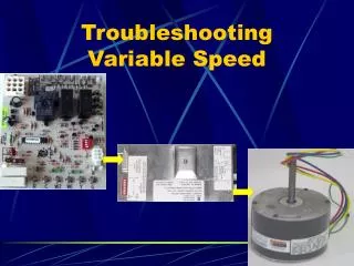
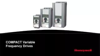
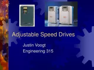
VARIABLE SPEED DRIVES. WHAT IS VARIABLE SPEED DRIVES?.

E N D
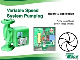
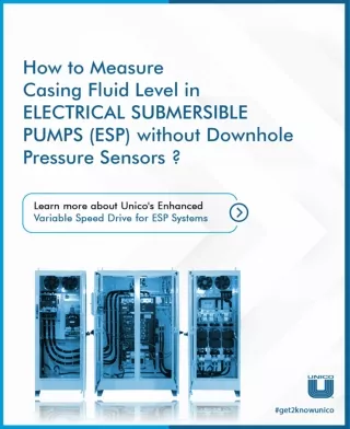
WHAT IS VARIABLE SPEED DRIVES? A variable speed drive (VSD), also known as a frequency converter, adjustable speed drive or inverter, is an electronic device that controls the characteristics of a motor’s electrical supply. Therefore, it is able to control the speed and torque of a motor, achieving a better match with the process requirements of the machine it is driving. So in applications where variable control is desirable, slowing down a motor with a VSD does reduce energy use substantially.
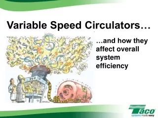
WHY VARIABLE SPEED DRIVES ? Save energy and improve efficiency Process controllability Reduced mechanical wear and shock Improved power factor Coordination of motion on various shafts Easy interfacing with automation systems
BENEFITS OF VARIABLE SPEED DRIVES • In addition to energy savings and better process control, VFDs can provide other benefits: • A VFD may be used for control of process temperature, pressure or flow without use of a separate controller. Suitable sensors and electronics are used to interface driven equipment with VFD. • Maintenance costs can be lowered, since lower operating speeds result in longer life for bearings and motors. • Eliminating throttling valves and dampers also does away with maintaining these devices and all associated controls. • A soft starter for motor is no longer required. • Controlled ramp-up speed in a liquid system can eliminate water hammer problems. • Ability of a VFD to limit torque to a user-selected level can protect driven equipment that cannot tolerate excessive torque.
Type of Drives Mechanical variable speed drives Hydraulic variable speed drives Electrical variable speed drives
Mechanical variable speed drives Belt and chain drives with adjustable diameter sheaves Metallic friction drives
Hydraulic variable speed drives Hydrodynamic types Hydrostatic types
Electrical variable speed drives DC Motor Drives Eddy Current Motor Drives AC Motor Drives
The workhorse of industry is the “ELECTRIC MOTOR” All of the machines mentioned earlier in the industries commonly driven by electric motors. It can be said that the electric motor is the workhorse of industrial processes. Now in this we will take a closer look at electrical motors - especially the squirrel cage AC motor with ac drives(VFD) , which is the most common motor used in industrial processes.
CONTROL PRINCIPAL OF VARIABLE SPEED DRIVES A VSD works by converting the incoming electrical supply of fixed frequency into a variable frequency output. This variation in frequency allows the drive to control the way in which the motor operates — a low frequency for a slow speed, and a higher frequency for a faster speed. The output can also be changed to enable the motor to generate more or less torque as required. So, the motor and drive combination might be used for turning a large load at fairly slow speeds, or turning a lighter load at high speeds, maximising efficiency.
Motor AC Line Diode Rectifier IGBT Inverter DC Bus Filter The speed of the rotating electric field within the induction motor. Synchronous Speed = 120 x frequency no. of motor poles • Diode rectifier converts AC line voltage to fixed voltage DC. • DC voltage is filtered to reduce current ripple from rectification. • Inverter changes fixed voltage DC to adjustable PWM AC voltage.
VFD Fundamentals A variable frequency drive converts incoming 50 Hz utility power into DC, then converts to a simulated variable voltage, variable frequency output AC DC AC RECTIFIER (AC - DC) INVERTER (DC - AC) 50 Hz Power Zero - 120 Hz 50 Hz VFD ABB To Motor Zero - 120 Hz Electrical Energy VFD
How Often You Switch From Positive Pulses To Negative Pulses Determines The Frequency Of The Waveform + Positive DC Bus Voltage - Negative DC Bus INVERTER RECTIFIER Frequency
Frequency = 30Hz Frequency = 60Hz
Selecting a variable speed drive Type of torque Whether a VSD is necessary Size required Type of control needed Potential savings
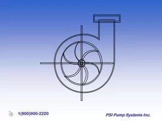
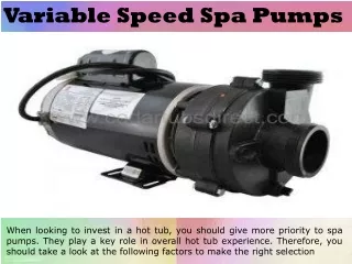
Various Types of Driven Equipments • Pump; • Fan; • Compressors; • Conveyers; • Mill; • Crusher; • Crane; • Hoist; • Traction; • Elevator
Affinity Laws, Centrifugal Pumps • Flow is proportional to speed • Pressure varies with square of speed • Power varies with cube of speed • Head pressure relative to flow increases at lower speeds
ASSUMPTION Consider a 10-horsepower motor that drives a centrifugal pump. The pump operates at full speed for 365 days annually, 24 hours each day. Cost of installation is 95,000 Rs Throttling cost of maintenance is 2100Rs/year Throttling efficiency is 67% VFD cost of maintenance 250Rs/year VFD efficiency is 98% The pump load schedule 20% time at 100% speed, 60% at 80% speed, 20% at 60% speed
Cost of fan running at full speed entire year: ( A)10HP x 0.746 kW/HP x 8760 hrs x 8Rs/kWh .67 = 780293.73Rs (B) Maintenance cost = 2100Rs Total cost per year 780293.73+2100= 782393.73
Cost after installation of VFD Cost of fan running at full speed entire year: ( A) 10HP x 0.746 kW/HP x 1752 hrs x 8Rs/kWh =106693.22 .98 (B) 10x 0.746 x 5256 x 8 x (0.80)3 =163880.8Rs .98 ( C ) 10 x 0.746 x 1752x 8x (0.60)3 = 23045.73 .98 ( D) Maintenance cost = 250Rs Total cost = 293869.75 Rs
TOATL SAVING 782393 - 293869 =488524Rs PAYBACK PERIOD 5000/488524 = .2 YEAR
Conclusion • Significant energy savings • Easy setup & programming • Retrofits • Space • Better design • Competitive edge
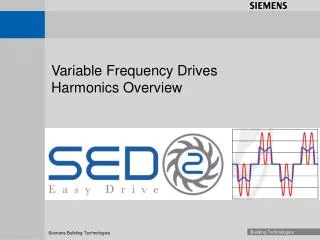
Effects of Harmonics • Previous slides referred to Current Distortion • Current Distortion results in Voltage Distortion • Potential for overheating of Transformers, Motors • Harmonic resonance • High neutral currents (1 ph - 3rd harm.)
The Load REGENERATION • When the rotor frequency is greater then the stator frequency the motor will begin to act like a GENERATOR. This will occur during deceleration and when the load drives the motor shaft. This GENERATED power is called REGENERATIVE ENERGY.
Stopping The Load LINE REGENERATIVE • A LINE REGENERATIVE motor control will route the REGENERATIVE energy from the motor back onto the input power line. Yes, this is desirable in applications where a significant amount of REGENERATIVE energy will be present such as engine dynamometers.