Download
1 / 26
260 likes | 264 Vues
Non- contact Safety Switches: D40R – RFID Coded D40P – Magnetic Coded. What is driving the need for the non-contact switches?. ISO 14119:2013 Safety of machinery -- Interlocking devices associated with guards -- Principles for design and selection Abstract

E N D
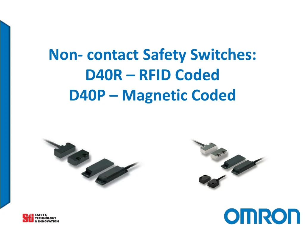
Non- contact Safety Switches: D40R – RFID CodedD40P – Magnetic Coded
What is driving the need for the non-contact switches? • ISO 14119:2013 • Safety of machinery -- Interlocking devices associated with guards -- Principles for design and selection • Abstract • ISO 14119:2013 specifies principles for the design and selection independent of the nature of the energy source of interlocking devices associated with guards. It covers the parts of guards which actuate interlocking devices. • ISO 14119:2013 provides measures to minimize defeat of interlocking devices in a reasonably foreseeable manner. Simpler means of applying and conforming to the standard
Non-contact Safety Switches High Level Coding Gap in Offering Gap in Offering MF CM MFS MA Application Requirements Low or Medium Level Coding D40Z/D40A Measures against Defeating Interlocks
D40R Combines RFID coding technology with IP69K ingress protection and standard mounting sizes. Basic (single – teachable) and uniquely coded models are offered. Unique coding (32,000,000 possible code) provides “high” tamper resistance in accordance with the standard ISO 14119. D40P Coded magnet using Hall Effect technology with long life, trouble free solid state outputs. Multiple sizes and case materials to meet the requirements of food & beverage, packaging and factory automation markets. IP69K / stainless steel versions; special food industry version mounts from the back with no front recesses, all have smooth mirror-polished surfaces. Provides “low” tamper resistance in accordance with the standard ISO 14119. Overview
Target Industries / Applications Target industry: • Food & Beverage • Packaging • Automotive Target applications: • Sanitary Packaging Lines • Material Handling/Palletizing • Robotic Welding Cells • Dirty Environments • Wet Environments • Packaging Machines D40P D40R
Food & Beverage Filling Machine D40P IP69K Stainless steel hygienic or special food type models
Packaging Roll-fed Thermoforming Machine D40R Highly tamper resistant (unique code versions),
Automotive / Metal Processing Non-ferrous cutting machine applications D40R D40P
Update Existing Applications Single keyed door switch can be easily bypassed or fail due to damage • Non-contact door switches can be added to existing applications to upgrade them to a higher performance level
D40P versus D40R Comparison BEST D40R-_B – RFID Unique Coding Impossible to defeat without actuator – 32 million codes High Tamper Resistance per ISO14119 BETTER D40R-_B – RFID Basic Coding Possible to defeat with SPARE actuator but needs re-teaching Low Tamper Resistance per ISO14119 GOOD D40P – Hall effect Coded Magnet Difficult to defeat without actuator Low Tamper Resistance per ISO14119
Clean In Place / Sanitized in Place (CIP/SIP) • D40P Coded Magnet Switches • IP69K Rating • Clean and Sanitize in Place • +105 C temperature rating • Stainless Steel Housings with “Ra4 Mirror Polish” finish • “Food” versions mount from back presenting smooth surface • Alternate solution • Plastic models can work from through stainless steel Safe for use with Clean-in-Place or Sanitize-in-Place Applications
High Tamper Resistance D40R-_U Unique actuators with 32,000,000 different codes High tamper resistance according to ISO 14119
No special controller required! D40P D40R Connect to virtually any Safety monitoring device with 2 NC inputs
Connect up to 20 switches in series <2mS Response Time Individual Operation indicators Individual Auxiliary Outputs … Door Closed Door Closed Door Closed Door Open Reduce the number of controllers required NOTE: PLd/Cat.3 when switches are connected in series
Wiring Accessories Up to 20 sensors in series T-Connector: Allows series connection of up to 20 sensors Connection Extension: Double-ended M12 Male to Female Cables End of Line Termination: Shorting Plug Any D40R/D40P-_-M12 model Any D40R/D40P-_-M12 model Any D40R/D40P-_-M12 model Simplify and quicken installation with fewer wiring errors NOTE: Auxiliary outputs are parallel connected; PLd/Cat.3 when switches are connected in series
Safety and Electrical Standards • EN ISO 14119:2013 Safety of Machinery. Interlocking Devices Associated with Guards, Principles for Design and Selection • EN ISO 13849-1:2008+AC:2009 Safety of Machinery, Part 1: General Principles for Design • EN 60497-5-3:2013 Low Voltage Switchgear and Control Gear – Part 5-3 • EN 62061:2005+AC:2010+A1:2013 Safety of Machinery, Functional Safety of Safety-related Electrical, Electronic and Programmable Electronic Control Systems • ANSI/UL 508 Industrial Control Equipment • CSA C22.2 No.14 Canadian Electrical Code • Additional D40R Approvals: • R&TTE Directive 1995/05/EC • EN301 489-1:V1.9.2 (04/2012), EN301 489-1:V1.6.1 (03/2013), EN301 330-2:V1.5.1 (08/2010) Up to PLe, (up to PLd in series)
D40P Plastic (IP67) Stainless Steel (IP69K) Hygienic (IP69K) Special Food Type (IP69K) D40R Plastic (IP69K / IP67) Diagnostic LED indicator Basic or Unique Coding All models LED operation indicator 5m, 10m or M12 pigtail options Common series connection accessories 2NC/1NO Solid state, polarity free outputs Models to Suit Most Applications D40P D40R
Printed Literature Separate Datasheets Combined 2-Page Flyer
Appendix: Technology Reed Switch Hall Effect Transistor Hall Effect Sensors are devices which are activated by an external magnetic field. We know that a magnetic field has two important characteristics flux density, (B) and polarity (North and South Poles). The output signal from a Hall effect sensor is the function of magnetic field density around the device. When the magnetic flux density around the sensor exceeds a certain pre-set threshold, the sensor detects it and generates an output voltage called the Hall Voltage, VH.
Appendix: Technology RFID How does an RFID system work?An RFID system consists of a tag, which is made up of a microchip with an antenna, and an interrogator or reader with an antenna. The reader sends out electromagnetic waves. The tag antenna is tuned to receive these waves. A passive RFID tag draws power from field created by the reader and uses it to power the microchip’s circuits. The chip then modulates the waves that the tag sends back to the reader and the reader converts the new waves into digital data.