Download
1 / 11
110 likes | 181 Vues
Motor Workbench ECE 498X – Winter 2010. Advisor: Professor Natarajan Amy Farris Tim Lukose Scott Stapleton. Department of Electrical and Computer Engineering University of Michigan – Dearborn. History.

E N D
Motor Workbench ECE 498X – Winter 2010 Advisor: Professor Natarajan Amy Farris Tim Lukose Scott Stapleton Department of Electrical and Computer Engineering University of Michigan – Dearborn
History U of M – Dearborn had an electric motor class and lab in the past. Hardware was becoming dated and original lab design was unsafe for students to work on.
Motor Workbench The Motor Workbench is a system to allow students to safely test AC and DC motors. • Main Components include • Test Motor – AC or DC motors and power for students to test • Load Motor – DC motor and power to provide a simulated load • Data Acquisition – Sensors on the motors to collect voltages, currents, and speeds of motors • Display and Store – PC user interface to analyze gathered data
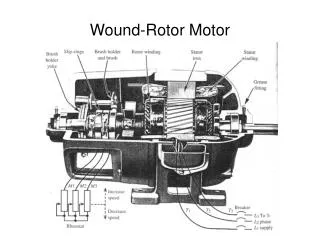
Specifications • Motors • 24V, 3 phase, AC induction motor and power • 90V DC motor and power • 24V Permanent Magnet motor • Microcontroller • Read up to 24Volts • Read up to 5 Amps • Read up to 1800 rotations per minute • Serial output to PC • PC • Graphical User Interface • Receive data
Data Acquisition – Amy Farris • Collect voltage, current, and speed from Load Motor Controller to Microcontroller (PIC16F690) • Collect voltage and current from Test Motor to Microcontroller • Send data serially to PC for analysis
User Interface – Tim Lukose Graphical display of motor data on PC Motor controls available Store motor data MATLAB chosen for interface program design
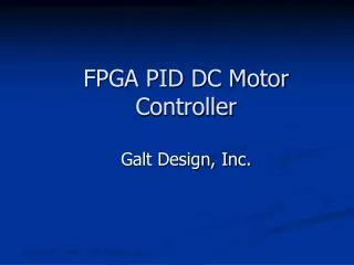
Motor Power – Scott Stapleton • Design 24V, 3 phase, AC power for induction motor • Configure Load Motor Controls and Power • Couple Load and Test Motors
Future Enhancements • 3 phase AC motor controller can be designed for variable speed testing • Labview could be considered for use
Acknowledgements • Professor Natarajan – Project Advisor • Professor Miller – ECE498x instructor & advisor • Tom Kowalski – Baldor Motors • Jesse Cross – Lab Technician assistance