Download
1 / 29
290 likes | 359 Vues
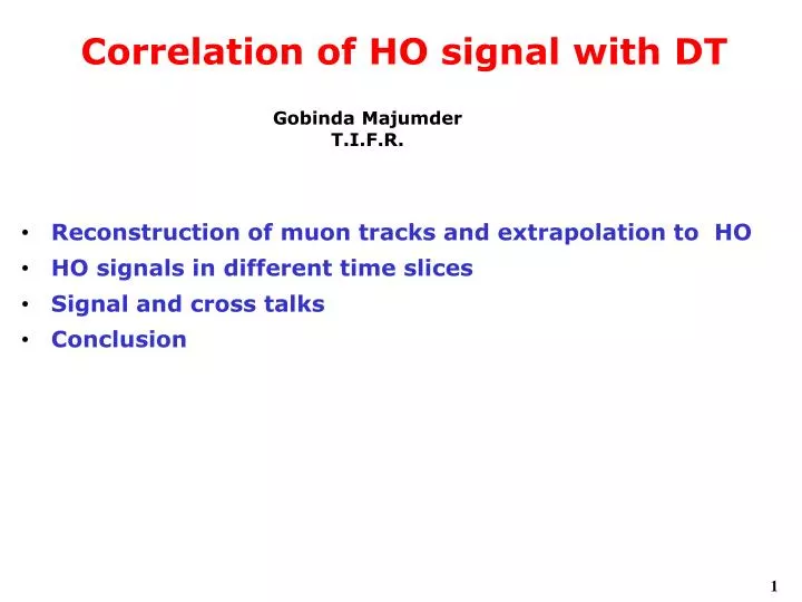
Gobinda Majumder T.I.F.R. Correlation of HO signal with DT. Reconstruction of muon tracks and extrapolation to HO HO signals in different time slices Signal and cross talks Conclusion. Drift Chamber information. Do not have data base for all runs

E N D
Gobinda Majumder T.I.F.R. Correlation of HO signal with DT • Reconstruction of muon tracks and extrapolation to HO • HO signals in different time slices • Signal and cross talks • Conclusion
Drift Chamber information • Do not have data base for all runs • Only databases from Run# 2377 (Bon) and Run#2255 (no field for MTCC-I) • Reconstruct DTRechit → DTRecSegment2D→DTRecsegment4D • 3.8T field (Run # 2559-2618): Use StandaloneMuon reconstruction code (modified for MTCC, but field map is for 4 Tesla) and then extrapolate to HO (only 30 cm away) • Extrapolation without any information of database • No field case (Run # 2476-2552): Use low uniform magnetic field (200 Gauss) to reconstruct muon track. • MTCC-II : 4412-4438 (4T) and 4446-4457 (ZERO) field : Only Ring2 timing are useful. 3986-4020 (3.8T), but many variation of timings and connections.
Cosmic ray muon spectrum in MTCC-I • Muon trigger is only in sector 10 (Vertically downward) • Momentum has to scale down by a factor 3.8/4 • Known problem : Ratio of μ+ and μ– are not 1.3 • Use muon with P>4 GeV and |θ–π/2|<0.5, |φ+π/2|<0.5, ndof>30 P (GeV) θ (rad)
Pixel configuration of Ring1&Ring2 • No difference in Ring1 and Ring2 • Look for signal in nearby six pixel (if there and also readout)
Time profile of Sector10, examples Phase-I YB2 • Variation of timing within few time period Phase-I YB1 Phase-II YB1 (3.8T) Phase-II YB2 (3.8T)
HO signals and cross talk • Signals only in Sector-10, φ=270o • Use only time slice 2-5 for MTCC-I • MTCC-II : 3-6 for Ring-I and 4-7 for Ring-2 • Pedestal is obtained from a single run, e.g., run# 3986 for data at 3.8T in phase-II • Signal to the extrapolated HO towers as well as nearest towers (pixel and physical position of tower) • To check random noise use same pixel in Ring-1(2), when extrapolated muon on Ring-2(1) • To have better accuracy of extrapolation, events are selected where muon hits inside 10cm of an edge of HO tile
Stability of pedestals Pedestal of all HO pixels for run# 3334-3338 • Pedestal values are stable over MTCC run period Variation of pedestal for different runs (two of them) Run # Run #
Signal in geometrically nearby tower • There are some +ve signals in geometrycally nearby towers, due to extrapolation or pixel cross talk or both ? η=–1 Φ=–1 η=–1 Φ=0 η=–1 Φ=+1 -10 (fC) 20 -10 (fC) 20 -10 (fC) 20 η=0 Φ=0 η=0 Φ=–1 η=0 Φ=+1 -10 (fC) 20 -10 (fC) 20 -10 (fC) 20 η=+1 Φ=0 η=+1 Φ=–1 η=+1 Φ=+1 -10 (fC) 20 -10 (fC) 20 -10 (fC) 20
Signal in geometrically nearby tower,but in different RM (ZERO field) ∆η=–1 ∆η=0 ∆η=+1 • Projection is not perfect, Muon reco/Extrapolation ? Projected φ=55 Signal in Φ=56 fC fC fC Projected φ=56 Signal in Φ=55 fC fC fC
Signal in geometrically nearby tower,but in different RM (3.8T field) ∆η=+1 ∆η=–1 ∆η=0 • Projection is not perfect, Muon reco/Extrapolation ? Projected φ=55 Signal in Φ=56 fC fC fC Projected φ=56 Signal in Φ=55 fC fC fC
Uncorrelated noise level (muon in YB1,signal in YB2) • In YB+1 case, we see some noise in presence of magnetic field B=0 YB=1 B=0 YB=2 fC fC B=3.8TYB=2 B=3.8TYB=1 fC fC
Signals in towers of nearest pixel, Ring1 without any field (H,15) • Little signal in nearby pixel Up left Up right QADC (fC) Left Projected Right Bot Left Bot right All six
Signals in towers of nearest pixel, Ring1 with B=3.8T (H,15) • Not much cross-talk, but signal height gone down Up left Up right QADC (fC) Left Projected Right Bot Left Bot right All six
Signals in towers of nearest pixel, Ring2 with 3.8T (H,15) • Little signal in up-right pixel Up left Up right QADC (fC) Left Projected Right Bot Left Bot right All six
Phase I data : Sector 10 @ZERO field • Statistical error ~1-3%. Total cross talk is 5-10%.
Phase I data : Sector 10 @3.8T field • Cross talk increase to ~15% for ring 1
Phase II data : Sector 10 @4.0T field • No visible change in signal and cross-talk
Comparison of means with and without B-field • There is no effect in ring-2, but ring-1 signal has gone down by a factor ~2, whereas cross talk is only about 10-25%
Comparison of HO signal and pedestal width in TB2006 & MTCC-I (no filed) TB2006 MTCC • Signal distribution is fitted with a (Gaussian (for ped)+Gaussian convoluted Landau (signal) in TB2006, for MTCC signal is fitted with only Gaussian convoluted Landau function Pedestal Pedestal fC fC Signal Signal fC fC
HO signal and pedestal width in TB2006 • qw peak/sigma Sigma
HO signal and pedestal width in MTCC(zero field) • Signal@ZERO field is comparable to TB2006 signal. Though signals are not consistent (in TB06 muons cover more path in the scintillator)
Conclusion • There is negligible cross-talk in Ring-2 pixel (~0.2T) • Ring-1 pixel shows increase in cross-talk of the level ~10% (0.3T) • Similarly uncorrelated noise is very low ~4×10⁻⁴ • Irrespective of cross-talk, total signal has gone down with magnetic field.
Angle between Bz/By vs z, important to eliminate HPD xtalk
2000, 2003 preditions vs 2006 Hall probe, By Field value also changes ! Field less than 0.2T (2kG) needed to have no discharges in HO
Bfield measurements with moving Hall probes (vladimir epshteyn, slava) 0,4T is no good, We want <0.2 T, need to displace box by ~70 cm 70cm Hall probes installed during mtcc1/mtcc2 shutdown data taken at 3.8T (Wednesday morning, oct-25-2006) And at 4.0T (Monday, oct-31-2006)