Download
1 / 31
310 likes | 312 Vues
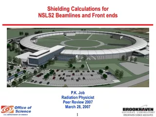
Summary of Shielding Calculations for NSLS2 Accelerators. P.K. Job Radiation Physicist Peer Review 2007 March 28 2007. Outline. Bulk Shielding Policy Calculational Tools and Procedures Beam Loss Assumptions Linac Shielding Design Storage Ring and Booster Shielding Electron Beam Stops

E N D
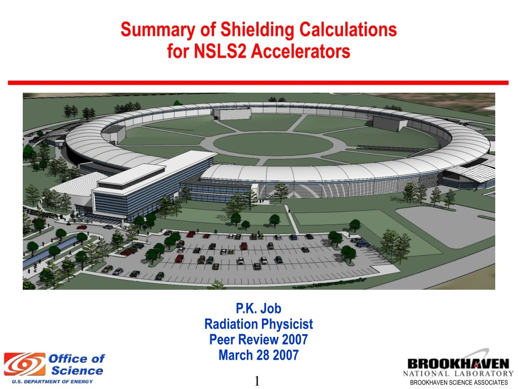
Summary of Shielding Calculationsfor NSLS2 Accelerators P.K. Job Radiation Physicist Peer Review 2007 March 28 2007
Outline • Bulk Shielding Policy • Calculational Tools and Procedures • Beam Loss Assumptions • Linac Shielding Design • Storage Ring and Booster Shielding • Electron Beam Stops • Supplemental Shielding in the Storage Ring
Desired Shielding Outcome • Compliance with DOE Orders, Part 835, and BNL Administrative Controls • < 25 mRem/year on-site to non-NSLS-II personnel; < 5 mrem/year at site boundary • Radiation exposure to users and staff ALARA – an administrative control level of 100 mRem/year is desired • We plan to achieve this through shielding and engineering & supplemental administrative controls • Based on current experience, we expect annual radiation exposures < < 100 mRem/year to NSLS staff and users
Shielding Policy • Accelerator enclosures & hutches shielded to 0.25 mrem/hr, 500 mRem/year based on 2000 hours of exposure per year at the exterior of the shield (< 0.5 mrem/h on contact) • Hutches are being considered further for 0.05 mRem/hr • They potentially represent a more significant source of exposure • Personnel more likely to be in vicinity of hutches
Shielding Policy (cont.) • Calculations use conservative shielding criteria and source terms • Abnormal operating conditions, including Maximum Credible Incidents (MCI), are evaluated • Additional engineering or administrative controls are specified based on severity of radiation levels under fault conditions. • Shielding and controls are considered adequate if MCI has low potential for exceeding 100 mRem and can not exceed 2000 mRem
Shielding Policy (cont.) Engineering control options include: • Additional shielding (e.g. shadow shields, localized shields) • Beam loss monitors with alarm in control room and (perhaps) interlock function • Area radiation monitors at the occupied areas with alarm locally and in control room and interlock function
Shielding Policy (cont.) Supplemental Administrative control options include: • Operational procedures for operators and ESH staff during injection and routine operations • Survey and posting procedures • Commissioning and shielding verification procedures • Shielding configuration control • Review of accelerator and beam design modifications • Passive area monitors
Radiation Sources Consideredfor calculations • Bremsstrahlung (High Energy Photons) • Bremsstrahlung produced Neutrons • Synchrotron Radiation (Low Energy x-rays)
Calculational Tools and Procedures • Semi-empirical Methods (Swanson, Shield11) • Analytical Methods (PHOTON, STAC8) • Monte Carlo Methods (EGS4)
LINAC Shielding LINAC Parameters used in Shielding Calculations • Beam energy 200 MeV • Beam current 20 nA • Bunch Pattern 500 pC/ 40 bunches • Frequency 1 Hz • Tunnel Length 60 meters • Tunnel width x height 4 x 3 m2 • Position of beam from floor 1 m • Power 4 watts
LINAC- Maximum Credible Radiation Incidents • 100 % of maximum accelerated beam is lost at some location in the linac enclosure, (20 nC/s is continuously lost) Dose Rate = 37.5 mrem/h (at the exterior of shield on contact) • 100 %injected beam to the booster is continuously lost at the linac-booster injection septum at 1 Hz. Dose rates at the exterior of the floor wall will be; Dose Rate = 15 mrem/h Mitigation/ control to prevent significant exposure • Area Radiation Monitors with beam shut off capability • Beam current monitors in the LINAC • Additional supplementary shielding at the septum/stop (lead/poly) • Operating procedures for operators during injection
Booster Parameters used in Shielding Calculations • Beam Energy 3.5 GeV • Repetition Rate 1 Hz • Accelerated Charge 15 nC • No of Electrons per Fill 9.36 × 10¹⁰ • Total Energy in the Booster 52.5 Joules • Interval Between Booster injections 72 sec (Normal operating mode)
Storage Ring Parameters usedin Shielding Calculations • Beam energy 3.5 GeV • Beam current 500 mA • Beam Life Time 2 hours • Tunnel Circumference 780 meters • Stored Charge 1.3 μC • Stored Electrons 8.1 × 10¹² • Stored Energy 4540 Joules • Interval between booster injections 72 Seconds (14 nC is lost in the Storage Ring in every minute)
Booster Bulk Shielding Estimates The Inboard and Outboard walls are at 1 m and the roof at 2 m from the beam
Storage Ring (Credible Radiation Incidents) • 100 % injected beam from the booster to storage ring is lost at any location in the storage ring (15 nC/s is continuously lost at some location other than injection region) Dose Rate = 277 mrem/h (at the exterior of the experimental floor wall on contact) • 100 % injected beam from the booster to storage ring is lost at any beamline front end due the shorting of a bending magnet (15 nC/s is continuously lost at a front end component) Dose Rate = 412 mrem/h (at the exterior of the ratchet wall ~ 0.5 m from the FE) (peak bremsstrahlung shielded with shadow shields) Mitigation/controls to prevent significant exposure • Area Radiation Monitors with beam shut off capability • Beam loss monitors inside the Storage Ring • Additional Supplementary Shielding (Shadow Shields) • Operating procedures for operators defining actions during injection
Bulk Shielding Comparison Bulk Shield at Experimental Floor Side cm
Beam Stop Dimensions Fe Beam Stop Dimensions for the 3.5 GeV e- Beam (to Contain 99 % of the EM Shower) e-Beam 4.2 cm (3 M) Fe Cylinder 35 cm (20 X0)
Shadow Shield Thickness 15 cm Pb
Radiation Shielding Design for NSLS II Shielding Design Documents 1. Linac, NSLS II- TN 12 2. Booster & Storage Ring, NSLS II – TN 13 3. Storage Ring Supplemental Shielding – TN 21 4. Beamlines and Front Ends, NSLS II – TN 14 5. Ray Tracing Standards, NSLS II – TN 20 6. Activation Analysis, NSLS II – TN 15 & 16