Download
1 / 39
460 likes | 791 Vues
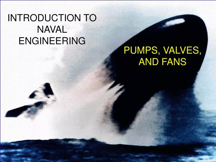
INTRODUCTION TO NAVAL ENGINEERING. PUMPS, VALVES, AND FANS. OBJECTIVES. How to control the flow of fluids. How to create flow of fluids in our system. Bernoulli’s Principle. Net Positive Suction Head (NPSH). Fans. VALVES. Globe Valve. Most common valve in a propulsion plant

E N D
INTRODUCTION TO NAVAL ENGINEERING PUMPS, VALVES, AND FANS
OBJECTIVES • How to control the flow of fluids. • How to create flow of fluids in our system. • Bernoulli’s Principle. • Net Positive Suction Head (NPSH). • Fans.
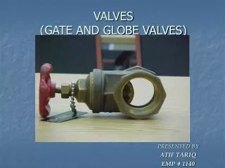
Globe Valve • Most common valve in a propulsion plant • Body may be straight, angle, or cross type • Valve inlet and outlet openings are designed to suit varying requirements of flow • Valve may be operated in the partially open position (throttled) • Commonly used in steam, air, oil and water lines
Gate Valve • Used for a straight line of flow where minimum restriction is desired • Not suitable for throttling • May be rising stem or nonrising stem
Ball Valve • Most ball valves are quick acting - only require 90o turn to completely open or shut valve • Some ball valves may have gearing for ease of use (also increases operating time) • Used in seawater, sanitary, trim and drain, air, hydraulic, and oil transfer systems
Butterfly Valve • Lightweight, relatively small, and quick acting • May be used for throttling • Used in freshwater, saltwater, lube oil, JP-5, F-76, and chill water systems
Check Valve • Allows fluid to flow in a system in only one direction • May be swing, lift, or ball type • Check valves may be built into globe valves or ball valves
Relief Valve • Installed in piping systems to protect them from excessive pressure • The relieving pressure is set by the force exerted on the disk by the spring • Relief valves may have a lever which allows manual opening of the valve for test purposes
Valve Operating Devices • Manual • Handwheel or lever is directly connected to the stem and is operated by hand • Hydraulic • Hydraulic pressure is applied to one side of a piston which is connected to the stem of the valve • Motor • A hydraulic, electric, or air driven motor is used to turn the stem of the valve • Solenoid • Uses an electromagnet to open or close a valve against spring pressure
Pump Components DRIVE TYPE (electric motor, steam drive, gear driven, etc…) IMPELLER PUMP SHAFT DISCHARGE CASING SUCTION
Pressure Head • Head • The vertical distance between two horizontal levels in a liquid • A measure of the pressure exerted by a column or body of liquid because of the weight of the liquid • Since a pump may be installed above, at, or below the surface of the source of supply, the pump must be able to overcome the net static head in order to pump from one elevation to another • Equal to Z + P/
Pressure Head NET STATIC HEAD STATIC DISCHARGE HEAD STATIC SUCTION PRESSURE PUMP
Velocity Head • Head required to impart velocity to a liquid • Equivalent to the vertical distance through which the liquid would have to fall to acquire the same velocity • Equal to V2 / 2g
Friction Head • The force or pressure required to overcome friction is obtained at the expense of the static pressure head • Unlike velocity head, friction head cannot be “recovered” or reconverted to static pressure head • Thermal energy is usually wasted, therefore resulting in a head loss from the system
BERNOULLI’S THEOREM • The Bernoulli equation is a special statement of the general energy equation • Work added to the system is referred to as pump head (hP), while losses from the system are referred to as head loss (hL)
Bernoulli’s Equation Z1 + (P1/) + (V12/2g) = Z2 + (P2/) + (V22/2g) + hP - hL Where: Z : Elevation (ft) P : Pressure (lb/ft2) : Density (lb/ft3) V : Velocity (ft/sec) g : acceleration (32.2 ft/sec2) Hp: pump head (ft) HL: Head Loss (ft) = f(L/D)(V2/2Zg) where f : friction factor L: Length D: Diameter
POSITIVE DISPLACEMENT PUMP • Fixed Volume • Volumetric Flow rate is proportional to speed • A relief valve will always be on the discharge end of the pump
Reciprocating Pump Characteristic Curve N2 = 2 N1 N1 N2 hP (ft) . V (gpm)
Pump Laws Apply to centrifugal (non-positive displacement) pumps only V N Hp N2 W N3 V = volumetric flow rate N = speed of rotation Hp = pump head W = power required (prime mover) . . .
PUMPS • Centrifugal: • Parallel pumps: V2 = 2V1 2 pumps HP HP2 = HP1 1 pump GPM V
PUMPS • Series (called staging): 2 pumps HP2 = 2HP1 HP V2 = V1 1 pump GPM V
NET POSITIVE SUCTION HEAD • Net Positive Suction Head: that pressure required at the suction of a pump to prevent cavitation. • cavitation: the formation of bubbles due to area where P < PSAT, and the subsequent collapse upon migration to a high-press. area. • causes noise and damage due to erosion and fatigue failure.
NET POSITIVE SUCTION HEAD • Need enough pressure on the suction side so that P < Psat. If P < Psat, water flashes to vapor causing damage to the pump. pump
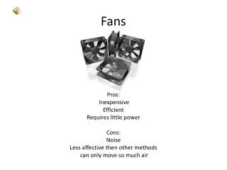
Fans • Operate on the same principle as non-positive displacement pumps: impart a velocity to a fluid and convert this kinetic energy into a pressure by the use of a diffusing chamber • Two types • Centrifugal: similar to a pump impeller, used in refrigeration compressors or gas turbine compressors in small gas turbine engines • Axial: similar to a propeller, used in forced-draft blowers
BERNOULLI’S THEOREM Z1 + P1/D + 1/2(V12/g) =Z2 +P2/D + 1/2(V22/g) + gc/g(wk) + HL Where: Z : Elevation (ft) P : Pressure (lbs/ft2) D : Density (lb/ft3) V : Velocity (ft/sec) g : acceleration (32.2 ft/sec2) wk: work (ft-lbs) HL: Head Loss = f(L/D)(V2/2Zg) where f : friction factor L: Length D: Diameter