Download
1 / 26
260 likes | 814 Vues
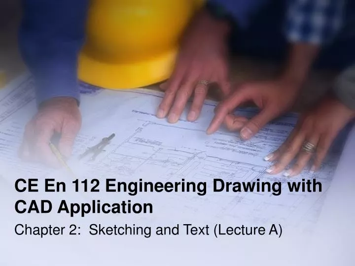
CE En 112 Engineering Drawing with CAD Application Chapter 2: Sketching and Text (Lecture A) Lecture Outline Technical sketching (2.1) Sketching technique (2.2) Proportions and construction lines (2.3) Introduction to projections (2.4) Multiview sketching technique (2.5)

E N D
CE En 112 Engineering Drawing with CAD Application Chapter 2: Sketching and Text (Lecture A)
Lecture Outline • Technical sketching (2.1) • Sketching technique (2.2) • Proportions and construction lines (2.3) • Introduction to projections (2.4) • Multiview sketching technique (2.5) • Multiview sketches (2.6) • Lettering (2.8) • Next class
Technical Sketching (2.1) • The process of producing a rough, preliminary drawing representing the main features of a product • Generally less finished, structured, or restricted, and less time for its creation • Tools include pencil, eraser, and paper (grid or blank) Means to create technical drawings Level of detail of freehand technical drawing
Technical Sketching (con’t) • Technical sketches: used extensively in the first (ideation) stage of the design process to explore and solidify design ideas that form in the mind’s eye
Technical Sketching (con’t) • Transforming your ideas into tangible graphic images serves both as a permanent record of those ideas and as a means of encouraging creative thinking • What’s the difference between the two figures below?
Technical Sketching (con’t) Rough sketch Multi-view sketch Shaded sketch Pictorial sketch
Sketching Technique (2.2) • Sketching is based on the interactive process of seeing, imaging (forming structure and meaning of visual data), and representing (creating sketches of what our mind sees).
Sketching Technique (2.2) • Practice Exercise 2.1 (p. 21) • Our perception is not limited to what we can see. Images often appear spontaneously in response to a memory recall. In this exercise, read the words and see if visual images are created in your mind’s eye. • Your bedroom where you grew up as a child, or the street you lived on. • A close relative, a famous actor, or a close friend from high school. • A basketball sitting at center court on your high school gym floor. • Your response to these written prompts is an example of your visual memory. You are thinking visually, which is a very powerful way of thinking when designing.
Sketching Technique (con’t) • What do you see?
Proportions & Construction Lines (2.3) • Proportion: • The ratio between two dimensions of an object • Represented by a series of preliminary (construction) lines, drawn light and fast, which may or may not represent the locations of the final lines in the sketch • The relative proportions of the primary dimensions of an object is more important than their actual physical sizes *Note: If a drawing doesn’t look or feel right, it probably isn’t
Proportions & Construction Lines (con’t) • Example of relative proportions: Standard proportions for the United States flag
Proportions & Construction Lines (con’t) • Creating a proportioned sketch: • Step 1: Gage the proportion of the overall size of the object. Lightly draw construction lines to create a bounding box • Step 2: Inside bounding box, draw major features of object • Step 3: Continue to draw bounding boxes until all features are represented • Step 4: Begin sketching the final line work (dark)
Introduction to Projections (2.4) • Projections: developed to represent 3-D images on 2-D media • Four basic types of projections: • Multiview • Axonometric • Oblique • Perspective • B, C, and D are pictorial because they represent the object as a 3-D form More to come in future lectures…
Multiview Sketching Technique (con’t) • Hidden line conventions must be followed in multiview sketching • Review these conventions and we will discuss them further in later lectures
Multiview Sketches (2.6) One-view, two-view, three-view sketches depending on the complexity of the object. Refer to the text for the steps in determining which to use – we will also discuss more in later lectures…
Multiview Sketches (con’t) Three image planes
Multiview Sketches (con’t) • Visualization Techniques: Object – Image plane – The eye of the reviewer relationship Horizontal, vertical, and depth
Multiview Sketches (con’t) Three types of faces: 1. Normal 2. Inclined
Multiview Sketches (con’t) 2. Inclined Inclined vs. Oblique faces: Can you tell the difference? 3. Oblique
Lettering (con’t) Lettering dimensions: Examples of lettering: