Download
1 / 42
430 likes | 893 Vues
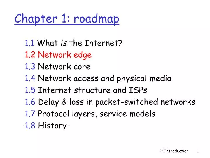
Chapter 1: roadmap 1.1 What is the Internet? 1.2 Network edge 1.3 Network core 1.4 Network access and physical media 1.5 Internet structure and ISPs 1.6 Delay & loss in packet-switched networks 1.7 Protocol layers, service models 1.8 History Brief Bio

E N D
Chapter 1: roadmap 1.1 What is the Internet? 1.2 Network edge 1.3 Network core 1.4 Network access and physical media 1.5 Internet structure and ISPs 1.6 Delay & loss in packet-switched networks 1.7 Protocol layers, service models 1.8 History 1: Introduction
Brief Bio • IBM (10 years): Programmer/manager AIX base operating system, manager of LAN (PCLP, PCNP) and PC/3270 software development • Dell Computer Corporation (4 years): manager software (firmware) development, V P of PC Products group • VTEL (4 years): senior VP development and general manager • eOn Communications (3 years): President & CEO • Bynari Inc (1 year): Chairman & CEO • UTA Faculty since Summer 2001 1: Introduction
My Hobby… and preferred mode of transportation 1: Introduction
end systems (hosts): run application programs e.g., WWW, email at “edge of network” client/server model client host requests, receives service from server e.g., WWW client (browser)/ Web server; email client/mail server peer-peer model: host interaction symmetric e.g.: teleconferencing, groupware, file sharing “connection” The network edge: 1: Introduction
Goal: data transfer between end sys. handshaking: setup (prepare for) data transfer ahead of time Hello, hello back human protocol set up “state” in two communicating hosts TCP - Transmission Control Protocol Internet’s connection-oriented service TCP service[RFC 793] reliable, in-order byte-stream data transfer loss: acknowledgements and retransmissions flow control: sender won’t overwhelm receiver congestion control: senders “slow down sending rate” when network congested The Internet's Connection-Oriented Service Network edge: connection-oriented service 1: Introduction
Goal: data transfer between end systems same as before! UDP - User Datagram Protocol [RFC 768]: Internet’s connectionless service unreliable data transfer no flow control no congestion control App’s using TCP: HTTP (WWW), FTP (file transfer), Telnet (remote terminal/login), SMTP (email) App’s using UDP: streaming media, teleconferencing, Internet telephony Network edge: connectionless service 1: Introduction
Chapter 1: roadmap 1.1 What is the Internet? 1.2 Network edge 1.3 Network core 1.4 Network access and physical media 1.5 Internet structure and ISPs 1.6 Delay & loss in packet-switched networks 1.7 Protocol layers, service models 1.8 History 1: Introduction
mesh of interconnected routers/switches the fundamental problem for the core: how to get data through an internet (network layer switching)? circuit switching: dedicated circuit per call, e.g. telephone network packet-switching: data sent thru net in discrete “chunks”, e.g. ?? The Network Core 1: Introduction
End-end resources reserved for “call” link bandwidth, switch capacity, queues/buffers dedicated resources: no sharing dedicated circuit-like (guaranteed) performance call setup required Network Core: Circuit Switching 1: Introduction
network resources (e.g., bandwidth) divided into “pieces” pieces allocated to calls resource piece idle if not used by owning call (no sharing) dividing link bandwidth into “pieces” frequency division (FDM) time division (TDM) FDM: 1 2 3 4 frequency time TDM: frequency time Network Core: Circuit Switching 1: Introduction
T1 Circuit 1.536 Mbps bandwidth, 24 time “slots” 500msec setup time Yields: 1.536Mbps/24 = 64Kbps per slot or “circuit” How long to send: 80KByte file? 1MByte file? Network Core: Circuit Switching TDM Example (80 * 103 * 8) / (64 * 103 ) = 640/64 = 10 (+ 0.5 sec = 10.5 sec) (1 * 106 * 8 ) / (64 * 103 ) = 8000/64 = 125 (+ 0.5 sec = 125.5 sec) 1: Introduction
each end-end data stream divided into packets users A & B packets share network resources each packet uses full link bandwidth resources used as needed, Bandwidth division into “pieces” Dedicated allocation Resource reservation Network Core: Packet Switching resource contention: • aggregate resource demand can exceed amount available • congestion: packets queue, wait for link use • store and forward: packets move one hop at a time • transmit over link • wait turn at next link 1: Introduction
Packet-switching versus circuit switching: human restaurant analogy other human analogies? D E Network Core: Packet Switching 10 Mbps Ethernet C A statistical multiplexing 1.536 Mbps B 45 Mbps queue of packets waiting for output link 1: Introduction
Takes L/R seconds to transmit (push out) packet of L bits onto link or R bps Entire packet must arrive at router before it can be transmitted on next link: store and forward delaytrans = 3L/R Example: L = 7.5 Mbits R = 1.5 Mbps delay (transmission) = 15 sec “message” switching vs. “packet” switching Packet-switching: store-and-forward L R R R 1: Introduction
Now break up the message into 5000 packets Packet Switching: Message Segmenting • Each packet 1,500 bits • 1 msec to transmit each packet on one link • pipelining: each link works in parallel • Delaytrans reduced from 15 sec to 5.002 sec 1: Introduction
1 Mbps link each user: generates traffic at 100Kbps when “active” is active 10% of time Capacity: circuit-switching: 10 users packet switching: with 35 users, probability > 10 active less than .0004 Packet switching allows more users to use (i.e. “share) the network! Packet switching versus circuit switching N users 1 Mbps link 1: Introduction
Great for bursty data resource sharing no call setup Excessive congestion (load): packet delay and loss protocols needed for reliable data transfer, congestion control Q: How to provide circuit-like behavior? bandwidth guarantees needed for audio/video and real-time applications in practice, solutions still evolving (chapter 6) Is packet switching a “slam dunk winner?” Packet switching versus circuit switching 1: Introduction
Goal: move packets through routers from the source (router) to the destination (router) we’ll study several path selection algorithms (chapter 4) datagram network: destination address determines next hop routes may change during session analogy: driving, asking directions virtual circuit network: each packet carries tag (virtual circuit ID), tag determines next hop fixed path determined at call setup time, remains fixed thru call routers/switches maintain per-call state Packet-switched networks: routing/forwarding 1: Introduction
Packet-switched networks Circuit-switched networks FDM TDM Datagram Networks Networks with VCs Network Taxonomy Telecommunication networks • A datagram network is not either connection-oriented or connectionless (i.e., it can be both). • The Internet provides both connection-oriented (TCP) and connectionless services (UDP) to apps. 1: Introduction
Chapter 1: roadmap 1.1 What is the Internet? 1.2 Network edge 1.3 Network core 1.4 Network access and physical media 1.5 Internet structure and ISPs 1.6 Delay & loss in packet-switched networks 1.7 Protocol layers, service models 1.8 History 1: Introduction
Q: How to connect end systems to edge router? residential access nets institutional access networks (school, company, organization) mobile access networks Key considerations: bandwidth (bits per second) of access network? shared or dedicated? Access networks and physical media 1: Introduction
Dialup via modem (PPP) up to 56Kbps direct access to router (conceptually, often less) not “always on” still most prevalent access means ADSL: asymmetrical digital subscriber line up to 1 Mbps home-to-ISP router (typically < 256 Kbps) up to 8 Mbps ISP router-to-home (typically < 1.5 Mbps) Uses FDM with 3 contiguous frequency bands downstream channel: 50 kHz – 1 MHz band upstream channel: 4 kHz – 50 kHz band telephone channel: 0 – 4 kHz band ADSL deployment: rapidly evolving Residential access: point to point access 1: Introduction
HFC: hybrid fiber coax (cable) asymmetric: up to 10Mbps downstream, 1 Mbps upstream requires cable modem at access point network of cable and fiber attaches homes to ISP router shared access to router among homes issues: congestion, dimensioning deployment: widely available via cable companies, e.g., AT&T(Comcast), AOL Time- Warner, Charter, etc. Residential access: cable modems 1: Introduction
Shared broadcast medium Residential access: cable modems Now, OC-192 Diagram: http://www.cabledatacomnews.com/cmic/diagram.html 1: Introduction
Cable Network Architecture: Overview Typically 500 to 5,000 homes cable headend home cable distribution network (simplified) 1: Introduction
Cable Network Architecture: Overview cable headend home cable distribution network (simplified) 1: Introduction
server(s) Cable Network Architecture: Overview cable headend home cable distribution network 1: Introduction
C O N T R O L D A T A D A T A V I D E O V I D E O V I D E O V I D E O V I D E O V I D E O 5 6 7 8 9 1 2 3 4 Channels Cable Network Architecture: Overview FDM: cable headend home cable distribution network 1: Introduction
company/univ. local area network (LAN) connects end system to edge router Ethernet: shared or dedicated cable connects end system and router 10 Mbps, 100Mbps, Gigabit Ethernet deployment: institutions, home LANs LANs: chapter 5 Institutional access: local area networks 1: Introduction
shared wireless access network connects end system to router wireless LANs: radio spectrum (unlicensed band) replaces wire e.g., Linksys 802.11g wider-area wireless access (MAN/WAN) CDPD: wireless access to ISP router via cellular network 3G/EV-DO, GSM, WAP WiMax/IEEE 802.16 router base station mobile hosts Wireless access networks 1: Introduction
Typical home network components: ADSL or cable modem router/firewall/NAT Ethernet wireless access point Home networks wireless laptops to/from cable headend cable modem router/ firewall wireless access point Ethernet (switched) 1: Introduction
physical link: transmitted data bit propagates across link guided media: signals propagate in solid media: copper, fiber unguided media: signals propagate freely, e.g., RF, IR Twisted Pair (TP) two insulated copper wires Category 3: traditional phone wires, 10 Mbps Ethernet Category 5 TP: 10/100/1000Mbps Ethernet Category 6 TP now standard: Up to 650 Mbps Physical Media 1: Introduction
Coaxial cable: wire (signal carrier) within a wire (shield) baseband: single channel on cable broadband: multiple channel on cable bi-directional use in 10Mbs Ethernet (10Base2) and cable networks Physical Media: coax, fiber Fiber optic cable: • glass fiber carrying light pulses • high-speed operation: • 100Mbps Ethernet • high-speed point-to-point transmission (e.g., 5 Gbps) • low error rate 1: Introduction
signal carried in electromagnetic spectrum no physical “wire” bi-directional propagation environment effects: reflection obstruction by objects interference Physical media: radio Radio link types: • terrestrial microwave • e.g. up to 45 Mbps channels • LAN (e.g., AirConnect) • 2Mbps, 11Mbps (802.11b) • 50+ Mbps (802.11a/g) • wide-area (e.g., cellular) • e.g. CDPD, 10’s Kbps • satellite • up to 50Mbps channel (or multiple smaller channels) • 270 msec end-end delay • geosynchronous versus LEOS 1: Introduction
Chapter 1: roadmap 1.1 What is the Internet? 1.2 Network edge 1.3 Network core 1.4 Network access and physical media 1.5 Internet structure and ISPs 1.6 Delay & loss in packet-switched networks 1.7 Protocol layers, service models 1.8 History 1: Introduction
roughly hierarchical at center: “tier-1” ISPs (e.g., Sprint, AT&T, MCI, Level3, Qwest, Cable & Wireless), national/international coverage treat each other as equals NAP Tier-1 providers also interconnect at public network access points (NAPs/MAEs) Tier-1 providers interconnect (peer) privately Internet structure: network of networks Tier 1 ISP Tier 1 ISP Tier 1 ISP 1: Introduction
Tier-1 ISP: e.g., Sprint Sprint US backbone network 1: Introduction
Tier-1 ISP: e.g., MCI MCI U.S. backbone network 1: Introduction
Tier-1 ISP: e.g., MCI MCI US-Intercontinental backbone network 1: Introduction
“Tier-2” ISPs: smaller (often regional) ISPs Connect to one or more tier-1 ISPs, possibly other tier-2 ISPs NAP Tier-2 ISPs also peer privately with each other, or interconnect at NAP • Tier-2 ISP pays tier-1 ISP for connectivity to rest of Internet • tier-2 ISP is customer of tier-1 provider Tier-2 ISP Tier-2 ISP Tier-2 ISP Tier-2 ISP Tier-2 ISP Internet structure: network of networks Tier 1 ISP Tier 1 ISP Tier 1 ISP 1: Introduction
“Tier-3” ISPs and local ISPs last hop (“access”) network (closest to end systems) Tier 3 ISP local ISP local ISP local ISP local ISP local ISP local ISP local ISP local ISP NAP Local and tier- 3 ISPs are customers of higher tier ISPs connecting them to rest of Internet Tier-2 ISP Tier-2 ISP Tier-2 ISP Tier-2 ISP Tier-2 ISP Internet structure: network of networks Tier 1 ISP Tier 1 ISP Tier 1 ISP 1: Introduction
a packet passes through many networks! Tier 3 ISP local ISP local ISP local ISP local ISP local ISP local ISP local ISP local ISP NAP Tier-2 ISP Tier-2 ISP Tier-2 ISP Tier-2 ISP Tier-2 ISP Internet structure: network of networks Tier 1 ISP Tier 1 ISP Tier 1 ISP 1: Introduction