Download
1 / 45
450 likes | 905 Vues
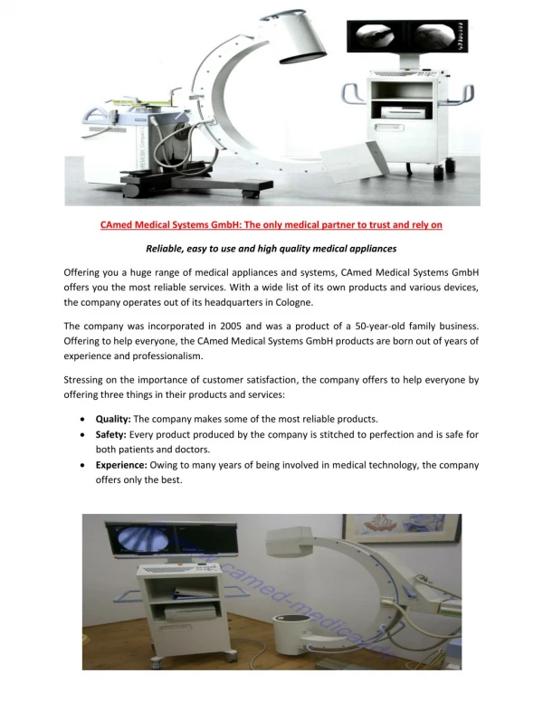
Ultrasound Boat Detection System A Worcester Polytechnic Institute Major Qualifying Project Advisor: Fabio Carrera Advisor: Peder Pedersen Students: Mark Johnson Jonathan Lovisolo Yasuhiro Okuno Presentation Overview System Block Diagram Real Environment Object Detection

E N D
Ultrasound Boat Detection System A Worcester Polytechnic Institute Major Qualifying Project Advisor: Fabio Carrera Advisor: Peder Pedersen Students: Mark Johnson Jonathan Lovisolo Yasuhiro Okuno
Presentation Overview • System Block Diagram • Real Environment • Object Detection • Boat Detection • Multiplexing (MUX) • Software Environment • Signal Processing • Intelligent System • Logging
Presentation Overview • Development Stages • Stage 1: Lab Environment • Stage 2: Portable System • Stage 3: Real Environment • Future Improvements • Wake Height Detection • Pressure Sensing
Boat Boat System Level Block Diagram At the Canal Software Environment on System Intelligent System Signal Processing MUX P/R Logging System Echo signal Data after Signal Processing Logged data • Echo • Signal: TRUE • Delay: 2 (ms) • Strength: 92 • Width: 96.2 (us) • Boat detected at: 2003-7-15-11:23:42 • Speed of boat: 14.1 (km/h) • Length: 6.3 (m) MUX: Multiplexer P/R: Pulser/Receiver
Operational Units • The following slides will describe the following different blocks of the system: • Signal Processing • Intelligent System • Logging System
Signal Processing • This begins the outline of the Signal Processing Section
Basic object detection using a transducer Beam Path Pulser/Receiver (P/R) Electric pulse sent by P/R to transducer Boat Hull Transducer Ultrasound pulse Pulser/Receiver (P/R) Transducer reacts by sending ultrasound pulse Boat Hull Transducer Echoed pulse Pulser/Receiver (P/R) Pulse hits object and echoes Boat Hull Transducer
Basic object detection using a transducer Echoed pulse Pulser/Receiver (P/R) Echo reaches transducer The transducer turns echo into electric pulse and sends it to P/R Boat Hull Transducer Pulser/Receiver (P/R) Electric pulse sent to the signal processing unit Signal Processing unit Transducer
Ultrasound pulses such as this are sent into the canal from the transducer Multiple Pulses Transducer System Individual Pulse
If this pulse is sent: The returning echo will look the same:
Boat Measured Echoes T = 0 Pulse sent
Boat Measured Echoes T = t1 Pulse echoed
Return Signal: When there is no boat No return signal Signal T 0
Signal Boat T 0 Return Signal: When there is a boat Clean echo signifying boat
Return Signal: When there are interferences Noisy and weak signal Signal T 0
Extracted Signal Information Signal width Signal strength Signal amplitude 0 0 T 2 x t1 Signal delay t1 is the time measured from the pulsing of transducer to when the pulse hit the boat hull So the time a signal takes to echo back to the transducer to “hear” is 2 x t1
Signal T 0 T 0 Extracted Signal Information: Correlation Sent Pulse Signal T 0 Received Pulse 1 (Clean) Received Pulse 1 (noisy) Echo is noisy and does not resemble sent pulse Low Correlation value Echo similar to sent pulse High Correlation value Correlation value of the signal, higher value means cleaner echo High correlation value means the echo came from a solid surface and not from interference
Once these four characteristics have been measured, Echo Validity can be determined Presence Correlation Echo Validity Amplitude Time Delay
Echo Validity determines if the pulse sent out is the same as the echo received. Pulse Echo Received Same? Echo Validity In this case, the echo received is the same as the pulse transmitted. Thus, echo validity is high.
Echo Validity determines if the pulse sent out is the same as the echo received. Pulse Echo Received Same? Echo Validity In this case, the echo received is dissimilar from the pulse sent out. Thus, the echo validity is very low.
So a stream of echo measurement such as below can be sent to the Intelligent System Validity Measurement
Echoes from the canal will only have a high validity if they are reflected off of a boat’s hard sides. Echoes with low validity correlate to reflections off of debris, birds, etc. If there is no echo, the echo validity is 0.
Intelligent System & Logging • The following slides will depict the Intelligent System design used to gather information about the boats, as well as how that information is logged
Basic Boat Detection Logic Ultrasound Beam • T = 0 • Boat is not intersecting the path of either ultrasound beam • System is idle Boat Canal Transducer • T = 1 • Boat is intersecting the path of left ultrasound pulse • System starts tracking the boat Boat Canal Transducer
Basic Boat Detection Logic • T = 2 • Boat is intersecting the path of both ultrasound pulses • Now the system ca calculate boat speed Boat Canal Transducer d • T = 3 • Boat just cleared off of the left ultrasound pulse • A boat just passed by! • Length of the boat can be now calculated Boat Canal Transducer
Multiplexer: Using 2 transducers in one channel Connected to P/R Multiplexer Pulser/Receiver (P/R) Switch signal from PC Disconnected from P/R Multiplexer Allows one P/R to alternately read from 2 transducers After receiving one switch signal from PC Disconnected from P/R Multiplexer Pulser/Receiver (P/R) Switch signal from PC Connected to P/R
Boat The Information passed to Intelligent System Transducer A Multiplexer Pulser/Receiver (P/R) Switch signal from PC Transducer B Into Signal processing Echo from transducer B Echo from transducer A Echo from transducer A Into Intelligent System Echo from transducer B Echo from transducer A Echo from transducer A Distance: 2.2 (m) Validity: 35 Distance: 2.0 (m) Validity: 67 Distance: 2.15 (m) Validity: 44 Time
The intelligent system then takes the signal data and makes final determinations on the presence of a boat. It looks at how many valid echoes are received consecutively with similar time delays. If there are enough valid echoes then a boat has passed.
There are enough valid echoes here. Therefore there is a boat Validity Measurement
This only has a few valid echoes. This was probably not a boat. Validity Measurement
Because debris, bubbles, or other factors can affect a signal we need to make the system allow for some invalid echoes. If a there is one invalid echo amidst a string of valid echoes we ignore it and go on.
Single bad echoes can be ignored. They could be caused by interference. Validity Measurement Bad Echo
If signals return with very different time delays then they are probably reflecting off of different boats. The system uses the time delay as a means of distinguishing between boats in the canal.
The two echoes had different delays because they hit different boats. Echo 1 Time delay Time delay Echo 2
The system sends pulses every 0.01 seconds. The system can keep track of how many pulses happen between when the boat hits Transducer A and Transducer B. The number of pulses tells the system how much time it took a boat to move a fixed distance. From this information we can calculate the speed of the boat. This was depicted earlier.
Boat Speed & length calculation Ultrasound Beam • Boat is not intersecting the path of either ultrasound beam • System is idle Boat Canal Transducer • Boat is intersecting the path of left ultrasound pulse • System starts tracking the boat Boat Canal Transducer
Boat Speed & length calculation • Boat is intersecting the path of both ultrasound pulses • Calculate speed of the boat: Boat Canal Transducer d • Boat just cleared off of the left ultrasound pulse • A boat just passed by! • Length of the boat can be calculated by: Boat Canal Transducer
When the system stops receiving valid echoes from a boat the speed is calculated. This was also shown earlier. Once this happens the information for the boat is logged. This information is printed in the log file like this: Timestamp: Sun Feb 16 14:30:07 2003 Speed: 9.7 km/h Length: 2.8 m Note: The length of this boat may be inaccurate due to other boats in the system! The note is shown when another boat interferes with the data for this boat.
Once the data is logged to a file it can be retrieved at any time. The system will be capable of retrieval by either disk or remotely through the internet when it is complete. Sample Entry in the log
Development Process The next few slides will depict the development process of this project By the end of the academic year, this group will have completed the second stage of development, ready for testing in Venice.
Toy Boat Development Stages: First Generation First Generation Fish Tank Pulser/Receiver Digitizer (LeCroy9400) GPIB PC with test software • Test of Theory in lab controlled environment • Test that the method works • Refine method of detection and data collection • Establish a detection software No new investment Using equipment available at WPI
Test Object (i.e. real boat) Development Stages: Second Generation Second Generation Pool/Venice Pulser/Receiver Laptop with digitizer card and test software • Field testing • Test theory established in first generation • Deal with any irregularity of the real environment • Finalize detection and data collection software Investment: Laptop $1500 Digitizer card $1300 P/R $2000 Transducer (x2) $800 * These Prices are rough estimates
Boat Development Stages: Third Generation Final Generation Standalone Embedded System Venice Canals Pulser/Receiver Data Transfer Via Network or Removable Media Research Team • Deployment • Implement all functionality developed in 2nd generation in a single standalone system. • Test all functionality in field • Deploy system for usage in Venice canals Price per Unit: Platform Hardware $500 - 800 Digitizer card $1300 P/R $2000 Transducer (x2) $800 * These Prices are rough estimates
Future Improvements: Wake height and pressure detection • In the Future… • Use Accelerometer or Pressure Transducer to measure force exerted on the wall. • This data can be used to relate traffic and canal damage Lateral Wave Force Boat Wake Height Accelerometer or Pressure Transducer With all the information, the log may look like the following for each station: (note: the values in the table is a sample and may not resemble real data) * The pressure measurement unit is unknown at the point of this writing, and the values may be unreasonably off
Conclusions • The project is currently in the second phase of development. • The second phase will be completed by May 2003, ready for testing in Venice • The system will be able to log: • Boat Traffic • Speed of Boats • Boat Size