Download
1 / 74
740 likes | 1k Vues
MOTION CONTROL. MPM UP2000 Hi-E SERIES PRINTERS. Steven Ng June 1999 Rev.3. At the end of this presentation, you will understand the theory behind motion control on the MPM UP2000 Hi-E stencil printer. Let’s get started !. Move Z Axis + direction !!!.

E N D
MOTION CONTROL MPM UP2000 Hi-E SERIES PRINTERS Steven Ng June 1999 Rev.3
At the end of this presentation, you will understand the theory behind motion control on the MPM UP2000 Hi-E stencil printer Let’s get started !
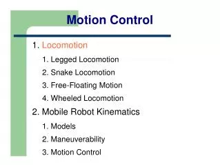
Move Z Axis + direction !!! UP2000 Hi-E Functional Block diagram (Motion) PC/ Software TV1 110VAC GS1 24VDC PCDIO Card Limit Sensor M Motion Control Card 32VAC TV2 Digital I/O Board # 1 Motion Mother Board 52VAC Bridge Rectifier 70VDC MUX Card Step Driver Software tells the MCC What to do !
UP2000 Hi-E Functional Block diagram (Motion) PC/ Software TV1 110VAC GS1 24VDC PCDIO Card Limit Sensor M Motion Control Card 32VAC TV2 Digital I/O Board # 1 Motion Mother Board 52VAC Bridge Rectifier 70VDC MUX Card Step Driver MOTION CONTROL CARD: ALL MOTION SIGNALS START AND END HERE !!!!!
Move Z Axis + direction !!! UP2000 Hi-E Functional Block diagram (Motion) PC/ Software TV1 110VAC GS1 24VDC PCDIO Card Limit Sensor OK, I will M Motion Control Card 32VAC TV2 Digital I/O Board # 1 Motion Mother Board 52VAC Bridge Rectifier 70VDC MUX Card Step Driver The MCC Receives the signal and does it’s thing
UP2000 Hi-E Functional Block diagram (Motion) PC/ Software TV1 110VAC GS1 24VDC PCDIO Card What’s behind Door # 40 ?? Limit Sensor M Motion Control Card 32VAC TV2 Digital I/O Board # 1 Motion Mother Board 52VAC Bridge Rectifier 70VDC MUX Card Step Driver It sends a signal through the MMB to the MUX to Open a channel or ( door )
UP2000 Hi-E Functional Block diagram (Motion) PC/ Software TV1 110VAC GS1 24VDC PCDIO Card Limit Sensor M Motion Control Card 32VAC TV2 Digital I/O Board # 1 Motion Mother Board 52VAC Bridge Rectifier 70VDC MUX Card Step Driver MOTION MOTHER BOARD: PASSIVE BOARD THAT HOLDS THE MUX BOARDS
UP2000 Hi-E Functional Block diagram (Motion) PC/ Software TV1 110VAC GS1 24VDC PCDIO Card Limit Sensor M Motion Control Card 32VAC TV2 Digital I/O Board # 1 Motion Mother Board 52VAC Bridge Rectifier 70VDC MUX Card Step Driver MOTION MOTHER BOARD: PASSIVE BOARD THAT HOLDS THE MUX BOARDS
UP2000 Hi-E Functional Block diagram (Motion) PC/ Software TV1 110VAC GS1 24VDC PCDIO Card Limit Sensor M Motion Control Card 32VAC TV2 Digital I/O Board # 1 Motion Mother Board 52VAC Bridge Rectifier 70VDC MUX Card Step Driver THERE ARE 4MUX CARDS ON THE MOTION MOTHER BOARD
MUX 1 THROUGH 4 ARE CONTROLLED BY MCC MCC MUX Card # 1 MUX Card # 2 MUX Card # 3 MUX Card # 4
MUX 1 THROUGH 4 ARE CONTROLLED BY MCC MCC MUX Card # 1 MUX Card # 2 MUX Card # 3 MUX Card # 4 Channel 0 = X Axis Channel 0 = Y Axis Channel 0 = Theta Axis Channel 0 = Z Axis Channel 1 = VX Axis Channel 1 = VY Axis Channel 1 = DSL Channel 1 = Transport Channel 2 = SQ Down Channel 2 = Spare Channel 2 = SQ Stroke Channel 2 = Tactile Channel 3 = Track Width Channel 3 = Paste Dispenser Channel 3 = Spare Channel 3 = Spare Channel 4 = Spare Channel 4 = Spare Channel 4 = Spare Channel 4 = Spare
Each MUX card has it’s own group of DRIVERS MUX Card Channel 0 Channel 4 Channel 1 Channel 3 Channel 2 Driver Card E # Driver Card E # Driver Card E # Driver Card E # Driver Card E #
UP2000 Hi-E Motion Schematic diagram Upper Drawer FROM MUX TO MOTOR ? Lower Drawer Motor How SIGNAL travels from MUX to Motor ?
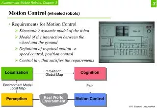
UP2000 Hi-E Motion Schematic diagram Signal travels through cable between P/J 44/45 to individual driver Upper Drawer P/J44 E1 : X-Axis E2 : Y-Axis E3 : Theta E4 : Transport P/J45 E5 : Z-Axis Lower Drawer E8 : SQ_DSL E11: Track Width E13: Tactile* Stepper Drivers E1 E2 E3 E4 E5 E6 E7 E8 E9 E10 E11 E12 E13 E14 E15 E16 *Note: Stepper driver E13 ( P4720 ) is different from other drivers ( P3251 )
UP2000 Hi-E Motion Schematic diagram Signal travels through cable between P/J 112/113 to individual driver Upper Drawer P/J112 E6 : SQ_Stroke E7 : SQ_Down E9 : VX E10: VY E12: Paste Dispenser P/J113 E14: Spare Lower Drawer E15: Spare E16: Spare Stepper Drivers E1 E2 E3 E4 E5 E6 E7 E8 E9 E10 E11 E12 E13 E14 E15 E16
UP2000 Hi-E Motion Schematic diagram Upper Drawer P/J112 P/J44 P/J113 P/J45 Lower Drawer Stepper Drivers E1 E2 E3 E4 E5 E6 E7 E8 E9 E10 E11 E12 E13 E14 E15 E16
UP2000 Hi-E Motion Schematic diagram In-Line Connector P86 P/J 133 Y Axis P87 P/J 134 Upper Drawer J86,87,88,89 X Axis Junction Box 1 P88 P/J 135 P/J112 P/J44 Transport P89 P/J 137 Track Width P/J 49 P/J113 P/J45 Lower Drawer
UP2000 Hi-E Motion Schematic diagram In-Line Connector P86 P/J 133 Y Axis P87 P/J 134 Upper Drawer J86,87,88,89 X Axis Junction Box 1 P88 P/J 135 P/J112 P/J44 Transport P89 P/J 137 Track Width P71 P/J 138 Paste Dispenser P72 P/J 128 SQ Down J71,72,73,74,183 Junction Box 3 P73 P/J 129 SQ Stroke P/J 49 P/J113 P/J45 P74 P/J 130 P/J 47 DSL Lower Drawer P183 P/J 197 Tactile
UP2000 Hi-E Motion Schematic diagram In-Line Connector P86 P/J 133 Y Axis P87 P/J 134 Upper Drawer J86,87,88,89 X Axis Junction Box 1 P88 P/J 135 P/J112 P/J44 Transport P89 P/J 137 Track Width P71 P/J 138 Paste Dispenser P72 P/J 128 SQ Down J71,72,73,74,183 Junction Box 3 P73 P/J 129 SQ Stroke P/J 49 P/J113 P/J45 P74 P/J 130 P/J 47 DSL Lower Drawer P183 P/J 197 Tactile P/J 48 J80 Junction Box 2 P80 P/J 131 Z Axis
UP2000 Hi-E Motion Schematic diagram In-Line Connector P86 P/J 133 Y Axis P87 P/J 134 Upper Drawer J86,87,88,89 X Axis Junction Box 1 P88 P/J 135 P/J112 P/J44 Transport P89 P/J 137 Track Width P71 P/J 138 Paste Dispenser P72 P/J 128 SQ Down J71,72,73,74,183 Junction Box 3 P73 P/J 129 SQ Stroke P/J 49 P/J113 P/J45 P74 P/J 130 P/J 47 DSL Lower Drawer P183 P/J 197 Tactile P/J 48 P/J 46 J80 Junction Box 2 P80 P/J 131 Z Axis P57 P/J 22 VY Axis J57,56,85 P56 P/J 21 Junction Box 5 VX Axis P85 P/J 127 Theta Axis
UP2000 Hi-E Motion Schematic diagram In-Line Connector P86 P/J 133 Y Axis P87 P/J 134 Upper Drawer J86,87,88,89 X Axis Junction Box 1 P88 P/J 135 P/J112 P/J44 Transport P89 P/J 137 Track Width P71 P/J 138 Paste Dispenser P72 P/J 128 SQ Down J71,72,73,74,183 Junction Box 3 P73 P/J 129 SQ Stroke P/J 49 P/J113 P/J45 P74 P/J 130 P/J 47 DSL Lower Drawer P183 P/J 197 Tactile P/J 48 P/J 46 J80 Junction Box 2 P80 P/J 131 Z Axis P57 P/J 22 VY Axis J57,56,85 P56 P/J 21 Junction Box 5 VX Axis P85 P/J 127 Theta Axis
UP2000 Hi-E Motor Reference Guide New Old Axis Assembly Remark P0991 “X” Axis, M1 1003309-1 990460/A “Y” Axis, M2 1003310-2 990460/A “Q” Axis, M3 1003310-3 990460/A “Vision X” Axis, M9 1003310-1 990460/A “Vision X” Axis, M9 *1005804 Retro 370 P1578 SQ Up/Dn, M7 1003312-2 PrHd,990461/A Track Width, M11 1003312-1 990461/A P3147 Paste Dispenser., M12 1003311-1 P3354 SQ Up/Dn, M7 1003308-1 Std Hd. 3.125A P3329 SQ Down Stop Limit, M8 1003307 P0809 Board Transport, M4 1003306-1 P5483 P0924 SQ Stroke, M6 1003318 P5482 P0831 “Z” Axis, M5 1003320-1 “Vision Y” Axis, M10 1003319 Tactile, M42 (Driver P4720) 1002440 Standard Head Tactile, M42 (Driver P4720) 1001935/C Bal. Control Hd *Note: Used together with coupling P6497, change driver Amp. From 2.5A to 3.125A
20 POSSIBLE AXES OF MOTION 4 AT ONE TIME
The signals for motion originate in the Motion Control Card. STEP DIRECTION MCC COMMON
The signals for motion originate in the Motion Control Card. STEP MCC TheSTEP signal triggers a green LED on the MCC in the computer. It can not be measured with a standard voltmeter
The signals for motion originate in the Motion Control Card. + 5VDC 0VDC DIRECTION MCC The DIRECTION signal does NOT trigger an LED. You can *measure the signal with a standard voltmeter. * Note: Hold the positive meter lead to the DIR wire (Pin 7) and common to the COM wire (Pin 1) at driver J1 connector, roll the trackball.
The signals for motion originate in the Motion Control Card. + 5VDC 0VDC DIRECTION MCC The signal is switched from +5VDC to 0VDC by changing the direction of the TRACKBALL.
The signals for motion originate in the Motion Control Card. + 5VDC 0VDC DIRECTION MCC This signal determines which direction the AXIS will move..... POSITIVE for +5VDC NEGATIVE FOR 0VDC
The signals for motion originate in the Motion Control Card. 4 Controls motors 10-14 20-24 30-34 40-44 MCC Each Card has 4 Channels for Signal OUTPUTS....
The signals for motion originate in the Motion Control Card. 4 Controls motors 10-14 20-24 30-34 40-44 MCC AND ...... 4 Channels for Signal INPUTS !
UP2000 Hi-E Functional Block diagram (Motion) PC/ Software TV1 110VAC GS1 24VDC PCDIO Card MUX # 4 Channel # 0 Limit Sensor M Motion Control Card 32VAC TV2 Digital I/O Board # 1 Motion Mother Board 52VAC Can I help you ? Bridge Rectifier 70VDC MUX Card Step Driver In this case it is Driver E5 or Mux 4 channel 0
UP2000 Hi-E Functional Block diagram (Motion) PC/ Software TV1 110VAC GS1 24VDC PCDIO Card OOHH, OK, Positive DIR. Here’s 5VDC Limit Sensor M Motion Control Card 32VAC TV2 Digital I/O Board # 1 Motion Mother Board 52VAC This Tickles ! Bridge Rectifier 70VDC MUX Card Step Driver At the same time, a 5VDC signal is sent on another Cable to the MUX for the driver signal.
UP2000 Hi-E Functional Block diagram (Motion) PC/ Software TV1 110VAC GS1 24VDC PCDIO Card Step, Step, Step Step, etc... Limit Sensor M Motion Control Card 32VAC TV2 Digital I/O Board # 1 Motion Mother Board 52VAC Oh Boy ! Step signal…. Bridge Rectifier 70VDC MUX Card Step Driver And a STEP signal is also sent to the MUX for the driver signal.
UP2000 Hi-E Functional Block diagram (Motion) PC/ Software TV1 110VAC GS1 24VDC PCDIO Card Step, Step, Step Step, etc... Limit Sensor M Motion Control Card 32VAC TV2 Digital I/O Board # 1 Motion Mother Board 52VAC Here Mr. Drive Now, DRIVE ! Bridge Rectifier 70VDC MUX Card Step Driver The Mux sends the STEP and DIRECTION Signals to the DRIVER...
UP2000 Hi-E Functional Block diagram (Motion) Our drivers operate on 65-70 VDC For VY, SQ. STROKE & Z AXIS The Model 6410 Drivers will not operate if the voltage exceeds 78VDC
Stepper Power Primary Voltage 208/220/240 VAC TV1 110VAC M How Does This Happen ? 32VAC TV2 52VAC Bridge Rectifier 70VDC Step Driver
UP2000 Hi-E Functional Block diagram (Motion) TV1 Transformer is a MULTI-TAP Transformer By changing the location of the incoming power on TV1, you can raise or lower the SECONDARY Power. TV1 110VAC ? TV2 ? 52 & 32 VAC ??? VAC
Primary Voltage IN at TV1 AC 208-240 240 VAC AC DC
0 104 110 120 0 208 220 240 Match Taps with Primary Voltage In TV 1 0 104 110 120 0 208 220 240 Output 110 V Simplified diagram of a multi-tap Transformer
Secondary Voltage at TV1 110 VAC AC DC
UP2000 Hi-E Functional Block diagram (Motion) TV1 110VAC TV2 TV3 32VAC 52VAC 32VAC Secondary Transformer There are two secondary step-down transformers in the lower drawer
UP2000 Hi-E Functional Block diagram (Motion) WAKE UP !!!!! 110V 32 VAC TV2 This is a Transformer that takes the Primary Voltage( 110V) and drops it to a Secondary Voltages. In this case it is dropped to: 52VAC 52 & 32 VAC
0 32 VAC 52 VAC Match Taps with Primary Voltage In 115 120 TV 2 Simplified diagram of a multi-tap Transformer
Secondary Voltage at TV2 52 VAC AC DC
Bridge Rectifier 70VDC UP2000 Hi-E Functional Block diagram (Motion) TV2 52VAC
Bridge Rectifier 70VDC UP2000 Hi-E Functional Block diagram (Motion) FROM AC TO DC VOLTS ? TV2 52VAC 52VAC is converted to 70VDC
Bridge Rectifier UP2000 Hi-E Functional Block diagram (Motion) Three Bridge rectifiers Located in Lower Drawer A Bridge Rectifier is a device comprised of 4 diodes that Changes AC volts to DC volts Our drivers operate on 65-70 VDC
UP2000 Hi-E Functional Block diagram (Motion) Rectifier Each Bridge Rectifier has it’s own Fuses in the Lower Drawer
UP2000 Hi-E Functional Block diagram (Motion) Capacitors: Our Machines use Capacitors in order to filter the DC Voltage to the Step Drivers. TV1 110VAC 32VAC TV2 52VAC Bridge Rectifier 70VDC • Capacitor