Download
1 / 53
740 likes | 1.13k Vues
3 rd Generation Synchrotron Light Sources. Francis Perez. Outline. 2. Synchrotron Radiation Synchrotron Light Sources 1st, 2nd, 3rd and Next Generation Enabling technologies Insertion devices Vacuum (NEG coating) Electronics (BPMs, LLRF, FOFB) Top UP Simulation tools

E N D
3rd Generation Synchrotron Light Sources Francis Perez
Outline 2 Synchrotron Radiation Synchrotron Light Sources 1st, 2nd, 3rd and Next Generation Enabling technologies Insertion devices Vacuum (NEG coating) Electronics (BPMs, LLRF, FOFB) Top UP Simulation tools …
Synchrotron Radiation 3 The theoretical basis for synchrotron radiation traces back to the time of Thomson's discovery of the electron. In 1897, Larmor derived an expression from classical electrodynamics for the instantaneous total power radiated by an accelerated charged particle. The following year, Liénard extended this result to the case of a relativistic particle undergoing centripetal acceleration in a circular trajectory. Liénard's formula showed the radiated power to be proportional to (E/mc2)4/R2, where E is particle energy, m is the rest mass, and R is the radius of the trajectory Arthur L. Robinson
Synchrotron Radiation 4 Early 20th century
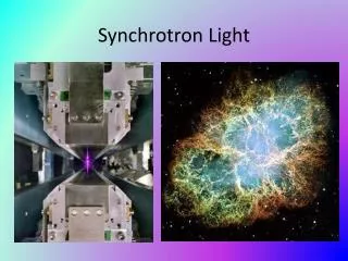
Synchrotron Radiation CRAB Nebulae Radiation from the Crab Nebulae is actually the synchrotron radiation of ultra relativistic electrons in interstellar magnetic fields Recorded by Chinese astronomers in 1054
Synchrotron Radiation Why an accelerator? “Synchrotron radiation are the electromagnetic waves emitted by a charged particle that moves in a curved trajectory at a speed close to the speed of light” Relativity equations Maxwell equations +
Why an accelerator? And combine both in an accelerator! ESRF
1st man-made synchrotron light Synchrotron light from the 70-MeV electron synchrotron at GE Synchrotron radiation was named after its discovery in a General Electric synchrotron accelerator built in 1946 and announced in May 1947 by Frank Elder, Anatole Gurewitsch, Robert Langmuir, and Herb Pollock in a letter entitled "Radiation from Electrons in a Synchrotron".
Synchrotron radiation Synchrotron Radiation Why an accelerator?
Why Synchrotron Radiation Interaction photons with matter Diffraction Reflection Photoemission fluorescence SAMPLE Photon beam Small angle dispersion Absorption Dispersion Information about sample properties
Why synchrotron light? Why Synchrotron Radiation • Continuous Spectrum: From infrared to X-rays Ecrit (keV) = 0.665 E2 (GeV) B(T) • Intense • Highly collimated: as a narrow stable beam Q(rad) = 0.51/E (MeV) • Polarized in the orbital plane • With temporal structure
Why Synchrotron Radiation Huge range of scientific disciplines, including condensed matter physics, chemistry, nanophysics, structural biology, engineering, environmental science and cultural heritage. Diamond Light Source dixit
Applications BIOLOGY GEOLOGY CHEMISTRY Catalysis Nucleosome High pressure High temperature ART microfluorescence MEDICINE INDUSTRY Manuscript 1679 Osteoporosys MATERIAL SCIENCE …and more Micromechanics
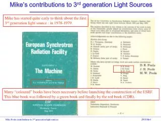
Synchrotron Generations 1st generation light sources (1956 - ) Accelerator built for High Energy Physics used parasitically for synchrotron radiation 2nd generation light sources (1981 - ) Accelerators built as synchrotron light sources 3rd generation light sources (1994 - ) Optimised for high brilliance with low emittance beam and Insertion Devices
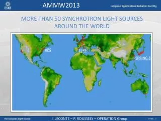
15 Synchrotron landmarks
Evolution Brightness Emittance 1980 100 nmrad 1990 10 nmrad 2000 3 nmrad 2010 1 nmrad … 2020 0.1 nmrad
1st Generation LS (1956 – …) 17 1968 Synchrotron Light experiment at NINA Ian Munro + Scott Hamilton (Manchester University)
1st Generation LS • 1968 Tantalus 1st Synchrotron Light Facility “Tantalus not only pioneered the use of synchrotron radiation, but created a research facility where both scientists and graduate students could perform hands-on work” A. Oswald 5 m
2nd Generation LS (1981 – …) SRS at Daresbury, UK 1st built accelerator for production of Synchrotron Light in the XR energy range Initially conceived for using the light from the bending magnets Bending magnet at SRS
2nd Generation LS (1981 – …) SOR-Ring Tokyo Japan 1976 SRS Daresbury UK 1981 DCI – LURE Orsay France 1981 NSLS Brookhaven USA 1982 BESSY Berlin Germany 1982 Photon Factory at KEK Tsukuba Japan 1982 MAX-I MAX-lab Sweden 1986 …
1981 ESRF
ESRF 3rd Generation LS (1993 – …) 1993 ESRF EU (France) 6 GeV ALS US 1.5-1.9 GeV 1994 TLS Taiwan 1.5 GeV ELETTRA Italy 2.4 GeV PLS Korea 2 GeV MAX II Sweden 1.5 GeV 1996 APS US 7 GeV LNLS Brazil 1.35 GeV 1997 Spring-8 Japan 8 GeV …
Insertion Devices WIGGLER to reach high photon energies UNDULATORS to generate high brilliance radiation
1998 NEG Coating Benvenuti C, Chiggiato P, Cicoira F, L’Aminot Y. J Vac Sci Technol A 1998;16:148. Coating the internal surface of a vacuum chamber with a Non Evaporable Getter (NEG) thin film. After thermal activation the oxide layer present at the NEG surface is dissolved, reducing significantly the secondary electron yield, the photon and the electron induced desorptions, and additionally providing high pumping speeds for the main gas species present in UHV systems.
NEG Coating Figure 1 – Global view of the coating facilities in building 181.
NEG Coating Since 2002, following collaboration and the purchase of a license from CERN, which holds the TiZrV NEG coating technology patent, the ESRF has been producing NEG coated vacuum and now many synchrotrons are usign it for narrow gap inserion devices.
1995 In 1995, Einfeld et al. PAC
Several developments were needed before considering it possible, since micron beam size required submicron beam stability • Orbit measurement • Beam stability • Beam lifetime • Reliable simulations • …
Thermal drifts ALBA data
2001SLS, Switzerland Users operation Top Up for User Operation
Thermal Stability XALOC: xBPM(y) Machine day Decay mode Top-up (jumps are due to changes in the ID gap, which needs recalibration of the xBPMs) ALBA data
2003 Fast Orbit Feedback Up to 100 Hz
Fast Orbit FeedBack 3 Hz horizontal kicker induced noise ALBA data
Injection schemes Conventional Pulsed Quad Oscillation from injection point to non-linear kicker *Phys. Rev. ST Accel. Beams 10, 123501, ‘New injection scheme using a pulsed quadrupole magnet in electron storage rings’, K. Harada, Y. Kobayashi, T. Miyajima, S. Nagahashi, Photon Factory, 2007. 39 39
2005 Pulsed Quad Kicker Proof of principle, but still no synchrotron light source has implemented it Stored beam unperturbed Injected beam receives a kick
Computation Computation capabilities increasing rapidly, allowing reliable simulations
MAX IV NEG Coating to reduce vacuum chamber dimensions and use of small magnets Multibend achromat, to reach 1 nmrad emittance Block magnet construction, relying fully on simulations Last generation of undulators Top Up Fast Orbit Feed back Multipole kicker injection (with standard injection as backup) …
Next:even lower emittance lattices • We need to master Nonlinear beam dynamics in order to optimise dynamic aperture and Touschek lifetime • MOGA – Multi-Objective (multi-parameters) Genetic Algorithms • Objectives: Dynamic aperture • Momentum aperture and lifetime • Tune shift with amplitude, dnx,y/dJx,y • Linear optics parameters • Variables: Sextupoles, Octupoles, Quadrupoles • Deterministic – Hamiltonian resonance driving terms analysis
PEP - X 7 Bend Achromat
Cancellation of resonances PEP-X: Baseline (2008) PEP-X: USR (2011) The dynamic aperture is in unit of sigma of the equilibrium beam size. The USR design is built with 4th-order geometric achromats and therefore no 3rd and 4th order resonances driven by the sextupoles seen in the scan.
Next Generation Light Sources Tevatron ULS 3 pm 8 pm at 1 Angstron Ultimate LS: Diffraction limited lattices
Workshop sessions included: Insertion devices, magnets and alignment Instrumentation for Low Emittance Rings Kicker systems RF system design, including low-level RF systems Vacuum design Feedback systems